Axewelledge, a leading exporter from India, specializes in high-quality Bentonite. With a commitment to excellence, we supply premium Bentonite to the Middle East and Southeast Asia markets.


North Angle Complex, 304,
150 Feet Ring Rd, Opposite Ambedkar Nagar BRTS Stop,
Madhav Park, Punit Nagar,
Mavdi, Rajkot, Gujarat 360004
© Axewelledge 2026, All Rights Reserved.
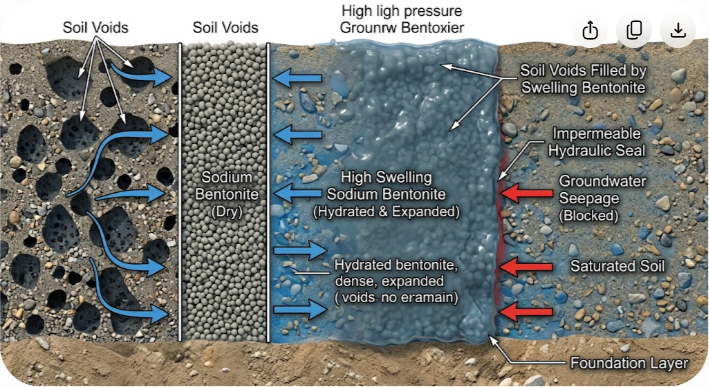
Water moves relentlessly through structural foundation pockets, micro-fractures, and porous soil matrixes. Left uncontained, groundwater seepage degrades concrete integrity, compromises slope stability in earthen dams, and leaches hazardous contaminants into surrounding aquifers. High swelling bentonite solves this challenge by transforming from a dry mineral clay into a dense, impermeable hydraulic barrier upon hydration.
Unlike synthetic membranes that risk tearing during backfilling or concrete placement, high swelling bentonite relies on active mineralogy. When exposed to moisture, its montmorillonite structure expands to 15–18 times its original dry volume. This swelling action exerts hydraulic pressure against surrounding boundaries, filling voids, self-healing punctures, and dropping soil permeability to levels below 1×10 ?9 cm/s.
Whether you are designing a deep foundation slurry wall, lining an industrial retention pond, or specifying a geosynthetic clay liner (GCL) for a municipal landfill, understanding the mechanics of high swelling bentonite is essential. Here is a technical breakdown of how this unique mineral operates, how to evaluate its hydraulic properties, and how to execute fault-free site installations.
To understand why bentonite prevents water movement so effectively, you have to examine its crystal structure. Bentonite is a volcanic ash weathering product composed primarily of smectite-group minerals, specifically montmorillonite.
Not all bentonite clays perform equally in civil engineering applications. The primary cation residing within the mineral interlayer space dictates its swelling capacity and hydraulic performance.
+ ) reside between the triple-layer crystalline sheets. Sodium has a large hydrated ionic radius combined with a single positive charge. When water enters the interlayer, it pushes the microscopic plates far apart, driving massive volumetric expansion (1200% to 1800%). This high swelling yields exceptionally low hydraulic conductivity.
2+ ) hold a double positive charge. This stronger electrostatic force binds the montmorillonite plates tightly together, limiting water absorption and restricting volume expansion to roughly 200% to 300%. While calcium bentonite works well in foundry casting or liquid purification, it cannot form an effective hydraulic barrier for heavy civil containment without extensive chemical modification.
When dry sodium bentonite contacts water, hydration occurs in two distinct phases:
$$ ext{Montmorillonite Clay Matrix} + H_2O longrightarrow ext{Cohesive Hydraulic Gel Zone}$$
This gelled matrix fills every adjacent capillary void within soil or aggregate mixtures, halting advective liquid flow.
High swelling sodium bentonite functions as the primary containment media across several core sectors of civil infrastructure.
Geosynthetic clay liners consist of a thin layer of high swelling sodium bentonite (typically 4.5 kg/m 2 to 5.0 kg/m 2 ) needle-punched or adhesively bonded between two geotextile fabrics. GCLs often replace or supplement thick compacted clay liners (CCLs) in landfills, secondary containment dikes, and mining leach pads. Their uniform thickness and low permeability make them an efficient alternative to traditional earthwork.
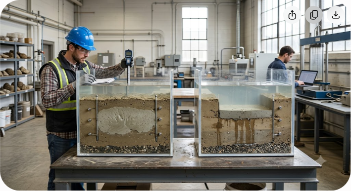
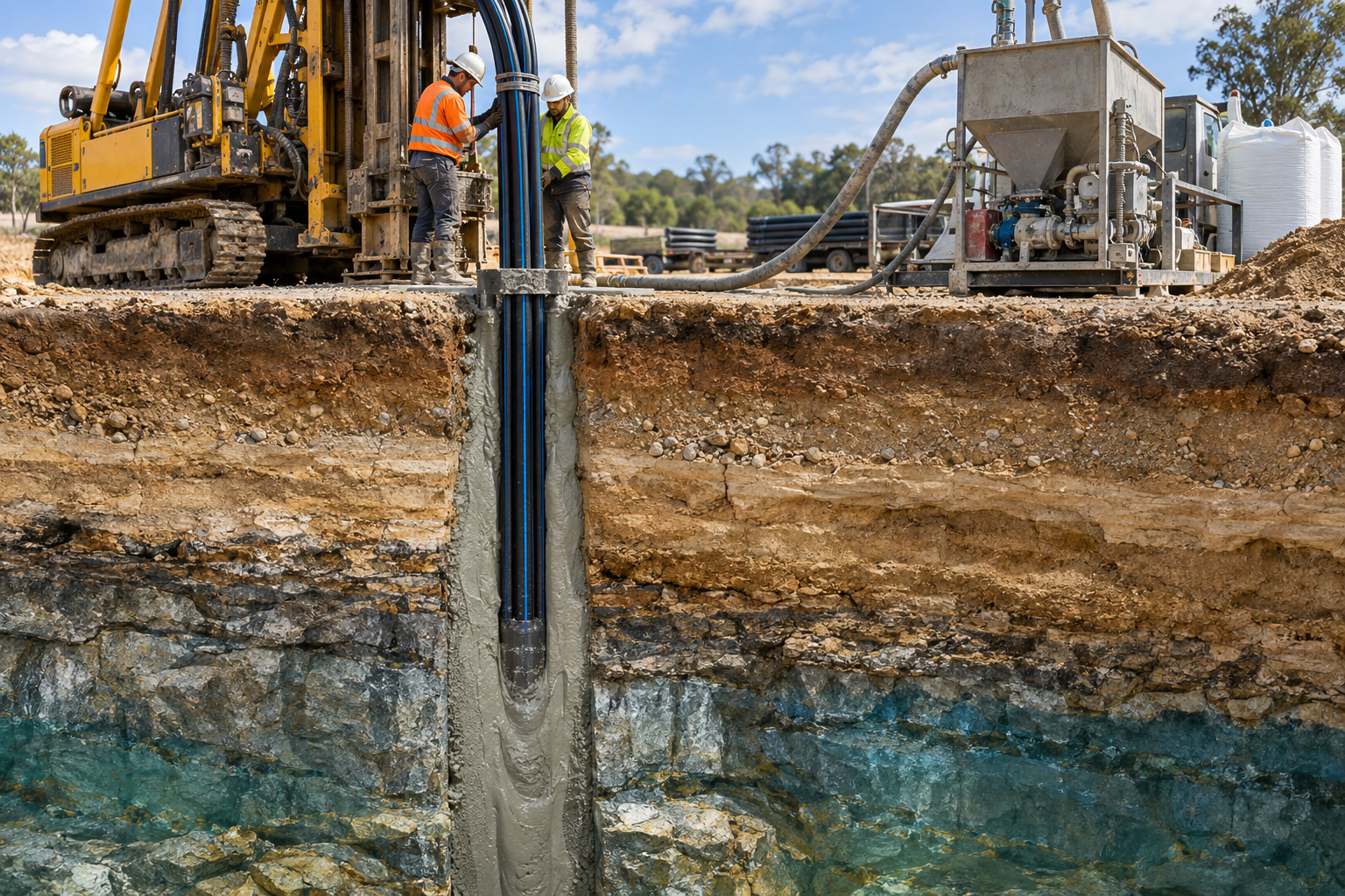
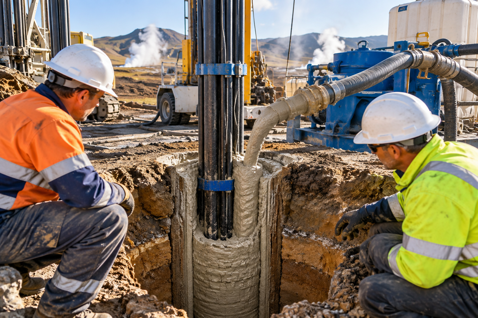
In deep excavation works and dam remediation, soil-bentonite slurry walls create vertical hydraulic barriers down to impermeable bedrock. During excavation, a 4% to 7% bentonite-water slurry stabilizes the trench walls by exerting hydrostatic pressure and forming a micro-thin, impermeable filter cake along the trench face. Afterward, workers backfill the trench with an engineered mixture of excavated soil, bentonite, and water to establish a continuous, low-permeability cutoff wall.
Post-applied and pre-applied bentonite sheet systems shield structural concrete basements, subway tunnels, and subterranean vaults from high groundwater tables. When subterranean water contacts the outer bentonite layer, the clay expands against the rigid concrete wall and surrounding backfill soil. This confinement turns the clay into a seamless waterproofing membrane that self-seals around small structural cracks or fastener penetrations.
Mixed directly into site soils at rates between 3% and 8% by dry weight, sodium bentonite transforms porous sand or gravel beds into watertight impoundments. It seals agricultural ponds, canal linings, and critical core zones inside earth-fill dams.
Selecting the right hydraulic barrier requires evaluating material durability, self-healing capability, installation conditions, and long-term performance metrics.
| Feature / Metric | High Swelling Sodium Bentonite | Compacted Clay Liner (CCL) | High-Density Polyethylene (HDPE) |
|---|
| Typical Hydraulic Conductivity (k) | 1×10 ?9 to 1×10 ?11 cm/s | 1×10 ?7 cm/s | <1×10 ?12 cm/s (intact) |
| Layer Thickness | 5 mm to 10 mm (GCL) | 300 mm to 900 mm | 1.5 mm to 2.5 mm |
| Self-Healing Capability | High (Expands to seal punctures) | Low (Prone to cracking under tension) | None (Punctures cause immediate leaks) |
| Differential Settlement Tolerance | Excellent (Flexible, plastic gel) | Poor (Cracks when deformed) | Moderate (Risk of stress cracking) |
| Freeze-Thaw Durability | Exceptional (Rehydrates without loss) | Poor (Desiccation cracks form) | High (Unaffected by freezing) |
| Installation Complexity | Low to Moderate | High (Requires heavy compaction) | High (Requires certified field welding) |
When writing project specifications for high swelling bentonite, generic soil classifications are not enough. You must establish strict quality control criteria according to standard ASTM test methods.
(XRD Analysis)
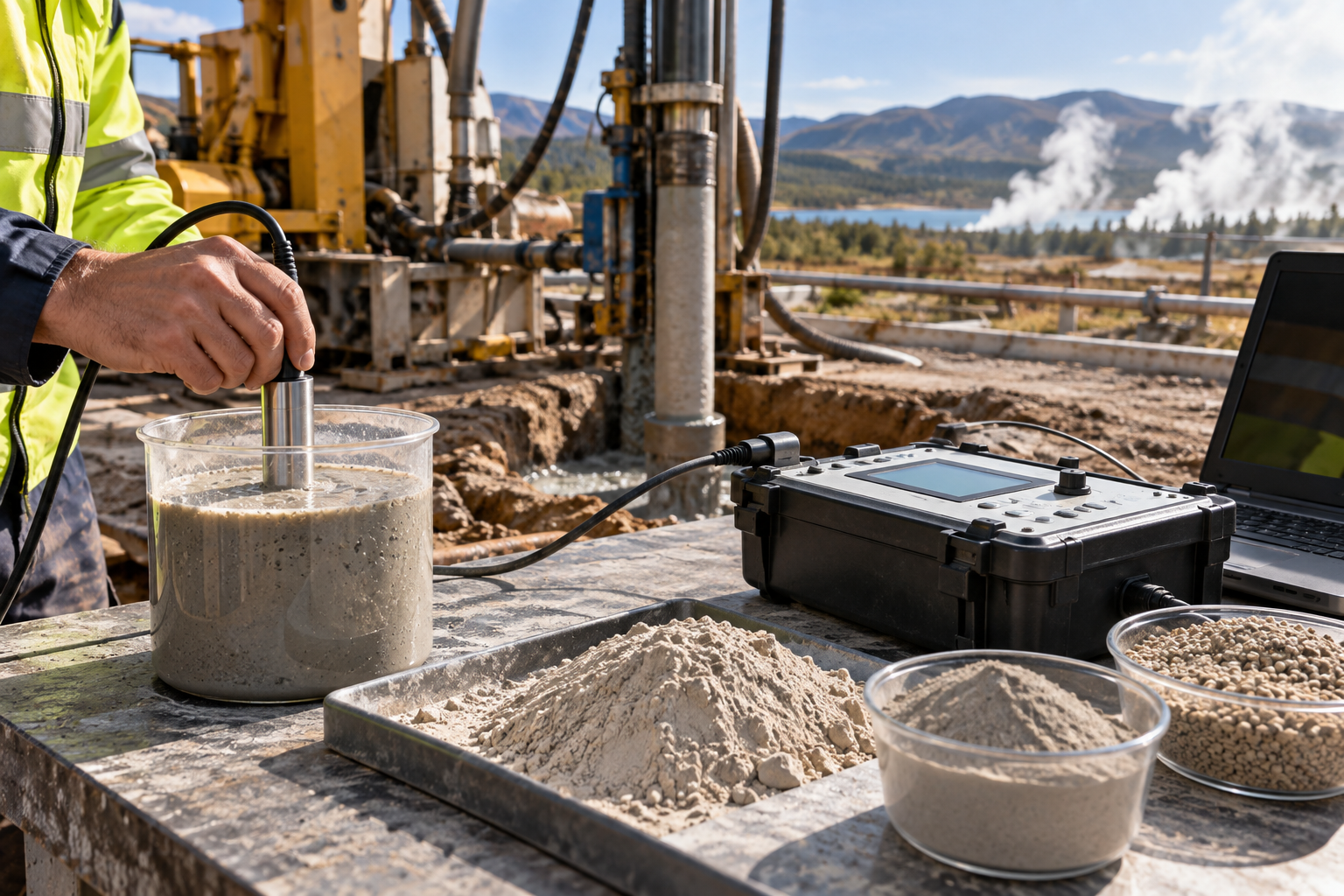
The Free Swell Index measures the unconfined volumetric expansion of bentonite in water. Two grams of oven-dried, finely ground bentonite are dusted incrementally into a 100 mL graduated cylinder filled with distilled water. High-grade sodium bentonite intended for civil containment must exhibit a free swell of at least 24 mL / 2g, with top-tier industrial grades exceeding 30 mL / 2g.
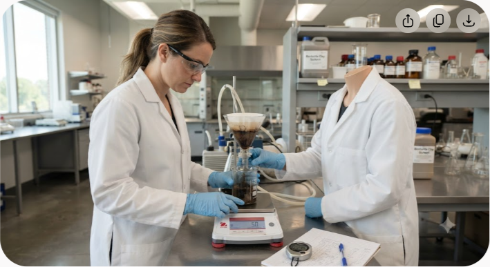
This test measures the volume of filtrate forced through filter paper under 100 psi (690 kPa) pressure when testing a standardized bentonite slurry. Lower fluid loss numbers indicate a tighter, less permeable filter cake. Target specifications generally require a fluid loss of less than 18 mL.
To maintain swelling capacity over decades, the bulk raw material should contain a minimum of 70% to 85% sodium montmorillonite by weight. The Exchangeable Sodium Percentage (ESP) should remain high relative to divalent calcium and magnesium ions. A high ESP ensures the clay resists rapid ion-exchange degradation when exposed to mineralized groundwater.
For drilling fluid and slurry wall applications, the bentonite must deliver high yield (measured in barrels of API-spec slurry per ton of material). High-yield bentonites yield a viscosity profile that suspends heavy soil cuttings while forming a stable filter cake along trench walls.
Even high-quality materials can fail if installed improperly in the field. Below are practical field procedures for two common application methods.
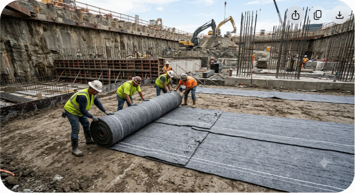
2 to 35 kg/m 2 , depending on target hydraulic conductivity). Spread granular or powdered sodium bentonite evenly using a calibrated mechanical spreader.
Modified Proctor).
While sodium bentonite is durable, specific site chemistry can degrade its swelling capabilities if not addressed during design.
When exposed to groundwater containing high concentrations of calcium (Ca 2+ ), magnesium (Mg 2+ ), or sodium chloride (NaCl), sodium bentonite undergoes cation exchange. Calcium ions replace original sodium ions within the clay structure, shrinking the interlayer spacing. This chemical transformation turns high swelling sodium bentonite into low-swelling calcium bentonite, causing a sharp rise in hydraulic conductivity.
In shallow liner installations exposed to severe drought, high swelling bentonite can lose moisture and form desiccation cracks. While high-grade bentonite naturally self-heals upon re-wetting, severe cyclic drying combined with root penetration can degrade performance over time.
During hydration, bentonite becomes a low-viscosity gel with low internal shear strength. On steep slopes (such as landfill side slopes or dam embankments), an unreinforced bentonite layer creates a potential slip plane.
A 22-meter deep commercial basement construction required continuous groundwater control in a high-water-table zone next to adjacent structures. Traditional sheet piling threatened ground vibration damage to neighboring foundations.
?10 cm/s) was placed into the trench.
A mining facility needed to build a 40-hectare wastewater and tailings impoundment over sandy, gravelly subsoils.
Designing effective hydraulic barriers requires reliable raw materials. Mineral purity, consistent particle sizing, and strong sodium exchange capacity govern how well bentonite performs under field conditions.
As one of India's largest mine owners and global suppliers of high-grade bentonite, Axewelledge delivers premium sodium bentonite designed for civil engineering, geotechnical containment, and trench slurry construction. Backed by reserves of over 60 million tons, advanced processing plants, and international quality control, Axewelledge supplies material that consistently exceeds ASTM swelling and fluid loss standards.
Whether you need bulk granular sodium bentonite for soil stabilization or specialized grades for slurry wall formulation, working with an experienced mineral producer ensures your infrastructure projects remain dry and structurally sound for decades.
Before finalizing your civil seepage design, confirm the following engineering steps:

Have questions about our products? We're here to help!