Axewelledge, a leading exporter from India, specializes in high-quality Bentonite. With a commitment to excellence, we supply premium Bentonite to the Middle East and Southeast Asia markets.


North Angle Complex, 304,
150 Feet Ring Rd, Opposite Ambedkar Nagar BRTS Stop,
Madhav Park, Punit Nagar,
Mavdi, Rajkot, Gujarat 360004
© Axewelledge 2026, All Rights Reserved.
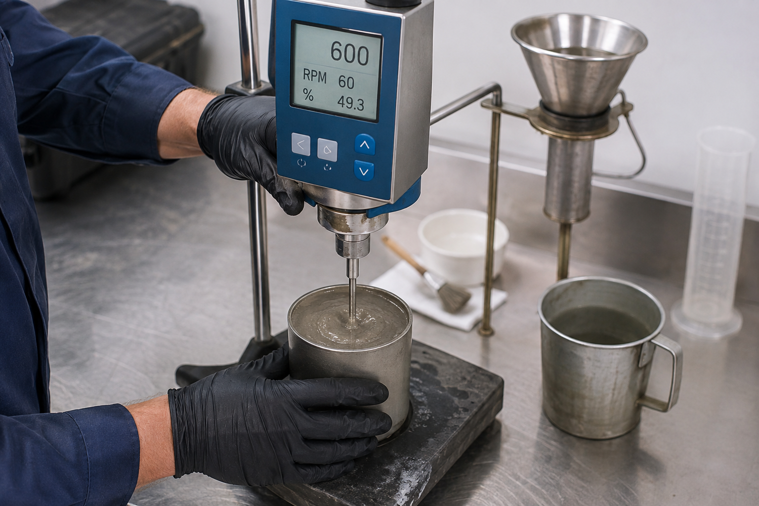
Measuring the Yield Point (YP) of Horizontal Directional Drilling (HDD) bentonite slurries requires a direct-indicating rotational viscometer (such as a Fann Model 35) to measure shear stress at 300 RPM and 600 RPM speeds. You calculate the Yield Point using the standard API formula: YP = (2 × 300 RPM dial reading) - (600 RPM dial reading), expressed in pounds per 100 square feet (lb/100 ft 2 ). While a Marsh Funnel measures overall fluid thickness, it cannot isolate yield point—making rotational viscometer field testing essential for effective hole cleaning and fluid maintenance.
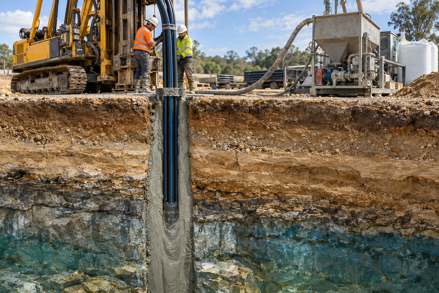
In horizontal directional drilling, poor hole cleaning leads directly to stuck pipe, high rotational torque, severe fluid loss, and inadvertent returns (frac-outs). Getting your slurry rheology right isn't just routine maintenance; it's the difference between completing a bore smoothly and losing a drill string.
Yield Point is a critical rheological parameter defined as the resistance to initial flow under applied stress. In simple terms, it measures the force required to break the electrochemical bonds formed between hydrated bentonite particles and set the slurry into motion.
Unlike Newtonian fluids like water or oil, which flow immediately upon the application of any force, bentonite slurries act as non-Newtonian, Bingham plastic fluids. They require a threshold level of force—the Yield Point—before they transition from a structured gel-like network into a flowing liquid.
| Fluid Type | Initial Yield Stress Required? | Shear-Thinning Behavior? | Primary HDD Function |
|---|---|---|---|
| Water (Newtonian) | No (Flows at 0 applied stress) | No (Viscosity stays constant) | Basic cooling and lubrication |
| Bentonite Slurry (Bingham Plastic) | Yes (Requires threshold stress = YP) | Yes (Viscosity drops under shear) | Carrying cuttings, suspending solids, sealing bore |
In horizontal directional drilling, gravity constantly pulls soil cuttings toward the bottom of the bore path. Unlike vertical oil well drilling, where cuttings fall parallel to the fluid flow, horizontal bores require the fluid to carry heavy sand, gravel, and clay particles along the floor of the tunnel.
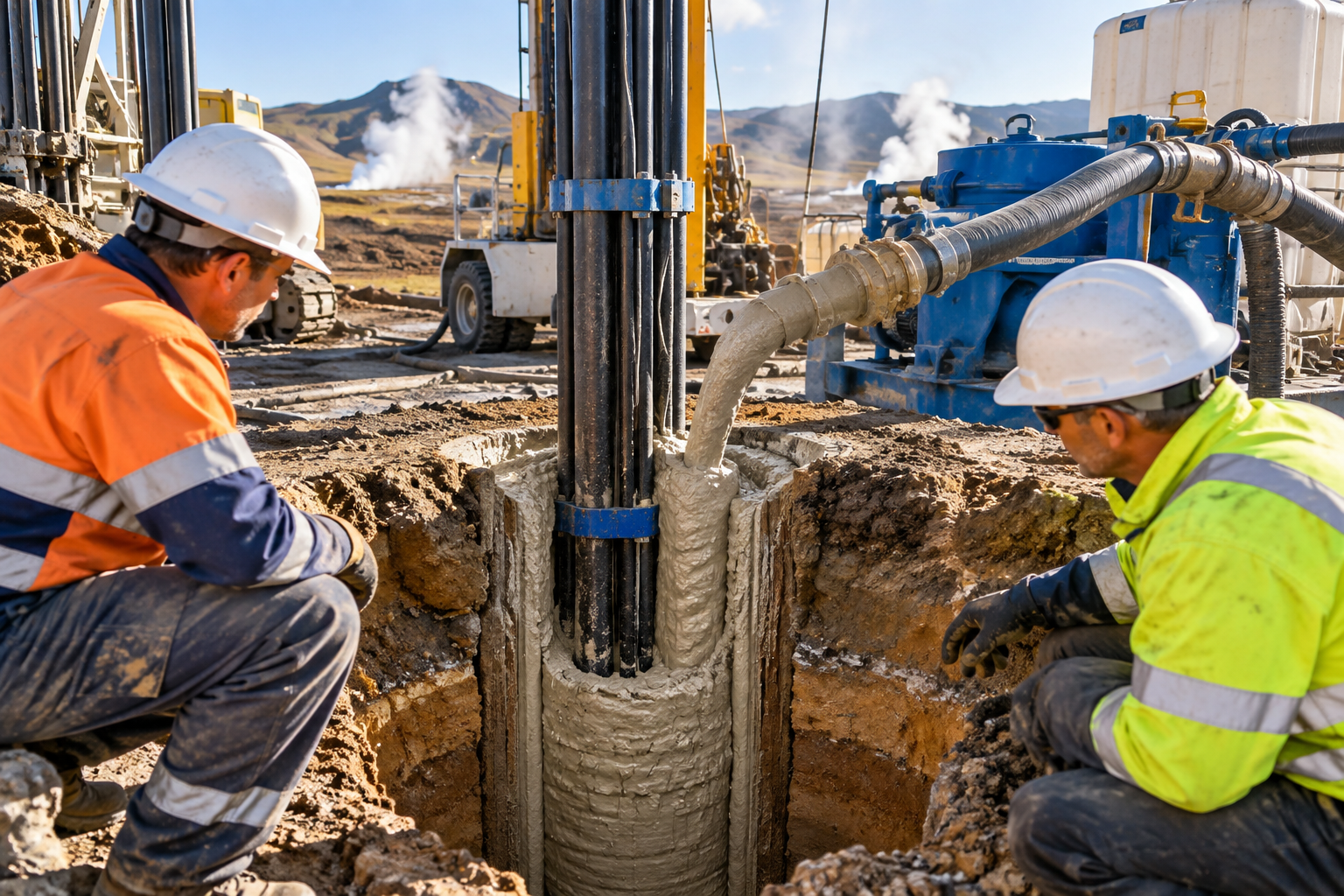
When your drilling slurry moves at lower annular velocities in reamed holes, Yield Point provides the dynamic lifting capacity required to keep heavy cuttings suspended in the moving stream. If the Yield Point is too low, solids rapidly settle out of suspension, forming a restrictive bed of cuttings along the bottom of the hole. This leads to:
Conversely, an excessively high Yield Point causes excessive circulating pressure losses, increased risk of hydro-fracturing fragile soil formations (frac-outs), and severe difficulty in screening solids out at the recycling plant.
Field operators often confuse Plastic Viscosity (PV) and Yield Point (YP) because both parameters are derived simultaneously using the same rotational viscometer. However, they represent fundamentally different physical mechanisms within the drilling fluid.
| Parameter | Underlying Cause | Control Factor | Field Management Action |
|---|---|---|---|
| Plastic Viscosity (PV) | Mechanical friction between solids and liquid phase | High concentration of fine solids, sand, and drill cuttings | Dilute with fresh water or run solids control equipment (desilters/centrifuges) |
| Yield Point (YP) | Electrochemical attractive forces between hydrated sodium bentonite platelets | Clay quality, hydration time, and pH condition | Add high-yield bentonite, polymer extenders (PAC/Xanthan), or chemical thinners |
Plastic Viscosity (PV) measures mechanical resistance caused by friction. This friction occurs between solid particles suspended in the fluid, between the solids and the liquid medium, and within the liquid layers themselves. High PV indicates that your fluid is choked with fine drilled solids (silt and sand), which drags down drilling efficiency and heats up downhole tooling.
Yield Point (YP) measures electrochemical attractive forces under dynamic flow conditions. High-quality sodium bentonite platelets carry negative charges on their flat surfaces and positive charges on their edges. In a well-hydrated slurry, these charges form a loose, dynamic three-dimensional structural network (often called a 'house-of-cards' structure) that lifts cuttings efficiently while flowing.
The ratio of Yield Point to Plastic Viscosity (YP/PV) gives drillers immediate insight into how efficiently the fluid carries cuttings relative to its mechanical friction. A high YP/PV ratio indicates a fluid with high lifting capacity and low mechanical drag—ideal for HDD operations.
Target an optimum ratio between 0.75 and 1.5 for most HDD applications. If the ratio drops below 0.5, your mud is overloaded with fine solids, rendering the Yield Point ineffective at cleaning the hole without generating destructive downhole pressures.
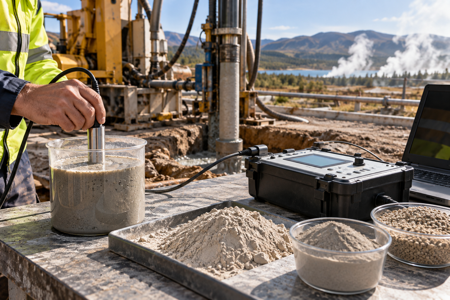
Accurately measuring Yield Point requires standard testing equipment designed according to API Recommended Practice 13B-1 (Field Testing Water-Based Drilling Fluids). Substituting makeshift tools or relying solely on a Marsh Funnel will compromise downhole stability.
| Viscometer Component | Physical Function | Field Purpose |
|---|---|---|
| Speed Switch (600 / 300 RPM) | Rotates sleeve at exact shear rates | Establishes standardized shear conditions for API calculations |
| Outer Rotor Sleeve | Spins in mud cup around inner bob | Applies rotational shear to the bentonite sample |
| Inner Bob & Torsion Spring | Deflects proportionally to fluid drag | Converts shear stress into dial scale displacement |
| Dial Reader Window | Displays numeric deflection units | Provides raw readings (R 600 ?
and R 300 ?
The primary instrument for measuring Yield Point is a two-speed or six-speed rotational viscometer (such as a Fann Model 35 or OFITE 8-Speed Viscometer). This instrument features an outer rotor sleeve and an inner stationary bob connected to a calibrated spring and dial.
When the outer sleeve rotates at fixed speeds (specifically 300 RPM and 600 RPM), the viscous drag of the fluid exerts a torque on the inner bob. This torque turns the dial against the spring, yielding direct shear stress readings.
A specialized fluid cup with an internal fill line ensures the rotor sleeve is immersed to the precise depth required for calibrated measurements.
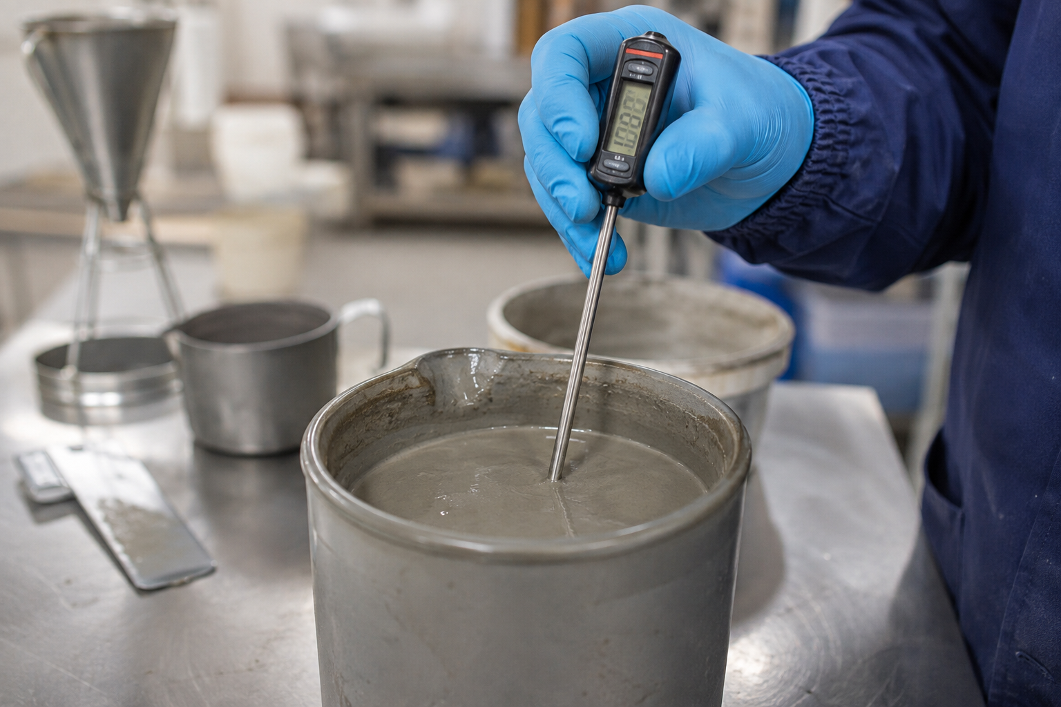
Temperature directly affects bentonite hydration and slurry rheology. Always record the temperature of the slurry sample when conducting testing (60 ? F to 120 ? F / 15 ? C to 49 ? C is standard).
Used for preparing field samples or re-shearing settled samples prior to testing to ensure uniform consistency.
Follow this precise standard operating procedure to determine the Yield Point of a water-based HDD bentonite slurry in the laboratory or field trailer.
Collect a fresh sample of drilling slurry directly from the active mud pit or pump discharge line. Avoid taking samples from stagnant corners of the pit where solids have settled. If testing return flows from the borehole, strain the sample through a 20-mesh screen to remove coarse drill gravel that could jam the viscometer sleeve.
Switch the viscometer to high speed (600 RPM) and allow the fluid to stir for 10 to 15 seconds. This breaks down any static gel structures formed while sampling and ensures thermal and structural homogeneity throughout the mud cup.
With the viscometer running steadily at 600 RPM, watch the dial on top of the instrument. Wait for the dial reading to stabilize (typically 10 to 20 seconds). Record this value as R 600 ?
.
Shift the speed gear or motor controller down to 300 RPM without stopping the motor. Allow the dial to stabilize again and record this value as R 300 ?
.
Before calculating Yield Point, determine the Plastic Viscosity using the formula: $$ ext{PV (cP)} = R_{600} - R_{300}
Calculate the Yield Point using the standard API equation:
SubstitutingtheformulaforPVyieldsthedirectcalculation:
To see how this works on an active job site, let's walk through two distinct real-world scenarios.
You take a fresh sample of active drilling fluid mixed with high-yield API grade sodium bentonite from your mud tank.
ext{Yield Point (YP)} = (2 imes 28) - 42 = 56 - 42 = 14 ext{ }lb/100 ext{ ft}^2$$ $$ ext{YP/PV Ratio} = rac{14}{14} = 1.0$$
Interpretation: This fluid exhibits an ideal balance. An YP/PV ratio of 1.0 indicates strong dynamic shear-thinning performance, offering robust cutting transport capability while maintaining manageable mechanical friction.
You collect a sample from the return flow pit during a long reaming run through fine silty clay.
600 ?
): 78
300 ?
Calculations: $$ ext{Plastic Viscosity (PV)} = 78 - 48 = 30 ext{ cP}
ext{Yield Point (YP)} = (2 imes 48) - 78 = 96 - 78 = 18 ext{ }lb/100 ext{ ft}^2$$ $$ ext{YP/PV Ratio} = rac{18}{30} = 0.6$$
Interpretation: While the Yield Point increased slightly (18 lb/100 ft 2 ), the Plastic Viscosity spiked dramatically to 30 cP due to an accumulation of ultra-fine drilled solids. The YP/PV ratio dropped to 0.6. This slurry will generate excessive pump pressures, run hot, and clean the hole inefficiently. Action required: Mechanical separation (centrifuge/desilter) and fresh water dilution.
Optimal Yield Point target values vary depending on the bore diameter, soil formation, and pullback phase. The table below outlines field-tested target guidelines:
| Soil Formation / Pipe Size | Recommended YP Range (lb/100 ft 2 ) | Target YP/PV Ratio | Primary Fluid Objective |
| :--- | :--- | :--- | :--- |
| Fine Sand & Light Silt | 8 – 14 | 0.75 – 1.0 | Prevent fluid loss, maintain stable wall cake |
| Coarse Sand & Small Gravel | 15 – 22 | 1.0 – 1.2 | High lifting capacity to float heavy solids |
| Cobble & Heavy Gravel | 22 – 32+ | 1.2 – 1.5+ | Maximum gel structural carry capacity |
| Reactive Clays/Shales | 10 – 16 | 0.8 – 1.0 | Inhibit clay swelling, prevent bit balling |
| Large Diameter Pullback (>24") | 18 – 25 | 1.0 – 1.3 | Keep continuous suspension over long durations |
One of the most common mistakes on small-to-medium HDD job sites is relying exclusively on a Marsh Funnel and viscosity cup to evaluate bentonite slurry performance.
| Feature | Marsh Funnel Viscometer | Direct-Indicating Rotational Viscometer |
|---|---|---|
| Measurement Type | Single-point overall flow resistance | Multi-point rotational shear stress |
| Shear Rate | Variable (decreases as funnel empties) | Fixed and calibrated (300 RPM, 600 RPM) |
| Output Unit | Seconds per quart (or liter) | lb/100 ft 2 (Yield Point) and cP (Plastic Viscosity) |
| Yield Point Isolation | No (Combines friction and electrochemistry) | Yes (Separates YP from PV via standard formula) |
A Marsh Funnel measures the time (in seconds) required for 1 quart (946 mL) of fluid to flow out of a standardized cone through a 3/16-inch orifice. As the liquid level inside the funnel drops during the test, the hydrostatic head pressure decreases, continuously altering the shear rate applied to the fluid.
Because non-Newtonian bentonite fluids change viscosity at different shear rates (shear-thinning behavior), a Marsh Funnel provides only a single, uncalibrated index of total flow resistance.
Consider two completely different bentonite slurries that both register a Marsh Funnel viscosity of 50 seconds/quart:
2 .
2 .
On paper, both fluids seem identical when using a Marsh Funnel. But downhole, Slurry A smoothly clears coarse sand and keeps the bore stable. Slurry B drops cuttings along the invert, causes high drag, and risks packing off the reamer.
Use your Marsh Funnel for rapid, minute-by-minute checks at the pit to catch major fluid shifts. However, verify your Yield Point using a rotational viscometer at least twice per shift.
When your measured Yield Point falls outside your target window, take targeted corrective action rather than randomly adding water or chemicals.
| Yield Point Status | Observed Field Symptoms | Corrective Action Steps |
|---|
| YP Too Low | Cuttings settling, sand bed formation, high pullback torque | 1. Add high-yield sodium bentonite.
| YP Too High | High circulating pressure, pump surging, screen blinding | 1. Dilute slurry with treated fresh water.
A low Yield Point results in poor hole cleaning, sand settling, and fluid loss into permeable gravel beds.
2 at low total solids concentration.
An excessively high Yield Point causes severe circulating pressure drops, surges downhole formations, and prevents solids equipment from screening out cuttings.
Accurate field measurements depend on proper instrument care and standardized procedure. Watch out for these four frequent operational errors:
Slurry viscosity drops as temperature rises. A sample pulled from a deep borehole at 105 ? F (40.5 ? C) will show a lower Yield Point if allowed to cool down to 65 ? F (18.3 ? C) in an air-conditioned field lab before testing. Always test samples immediately at their native temperature or record temperature for trend comparisons.
If your drilling slurry contains heavy sand (>2% by volume), coarse particles can settle to the bottom of the mud cup during lower RPM readings. This settling creates artificial mechanical drag against the bottom edge of the rotor sleeve, throwing off dial readings. Screen coarse sand out of the sample using a 20-mesh sieve before filling the cup.
Field viscometers endure harsh vibration and handling. Bent bobs, eccentric rotor sleeves, or stretched torsion springs yield incorrect dial numbers. Calibrate your viscometer quarterly using certified Newtonian calibration fluids (e.g., 50 cP oil standards).
High-shear mixing hoppers can trap fine air bubbles in the slurry. Entrained air decreases density and disrupts the continuous liquid phase, skewing viscometer dial readings. Allow aerated samples to stand undisturbed for 2–3 minutes or tap the cup gently to release air bubbles before lowering the viscometer head.
Achieving and maintaining optimal Yield Point starts long before adding specialty polymer additives—it begins with choosing high-grade base sodium bentonite.
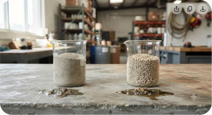
High-yield natural sodium bentonite, such as that mined and processed by global mineral producers like Axewelledge, naturally possesses exceptional swelling power and high cation exchange capacity. High-grade sodium bentonite releases billions of individual plate-like particles per cubic millimeter upon hydration. This extensive platelet surface area generates robust electro-chemical structures at modest addition rates, yielding a high Yield Point without overloading the system with un-hydrated solids.
By starting with a pure, high-quality sodium bentonite base, HDD contractors eliminate the need for costly secondary chemical additives, lower overall mud tank maintenance costs, and ensure consistent hole cleaning across changing soil conditions.
300 ?
)?R 600 ?
to isolate electro-chemical carrying capacity from mechanical friction.


Have questions about our products? We're here to help!