Axewelledge, a leading exporter from India, specializes in high-quality Bentonite. With a commitment to excellence, we supply premium Bentonite to the Middle East and Southeast Asia markets.


North Angle Complex, 304,
150 Feet Ring Rd, Opposite Ambedkar Nagar BRTS Stop,
Madhav Park, Punit Nagar,
Mavdi, Rajkot, Gujarat 360004
© Axewelledge 2026, All Rights Reserved.
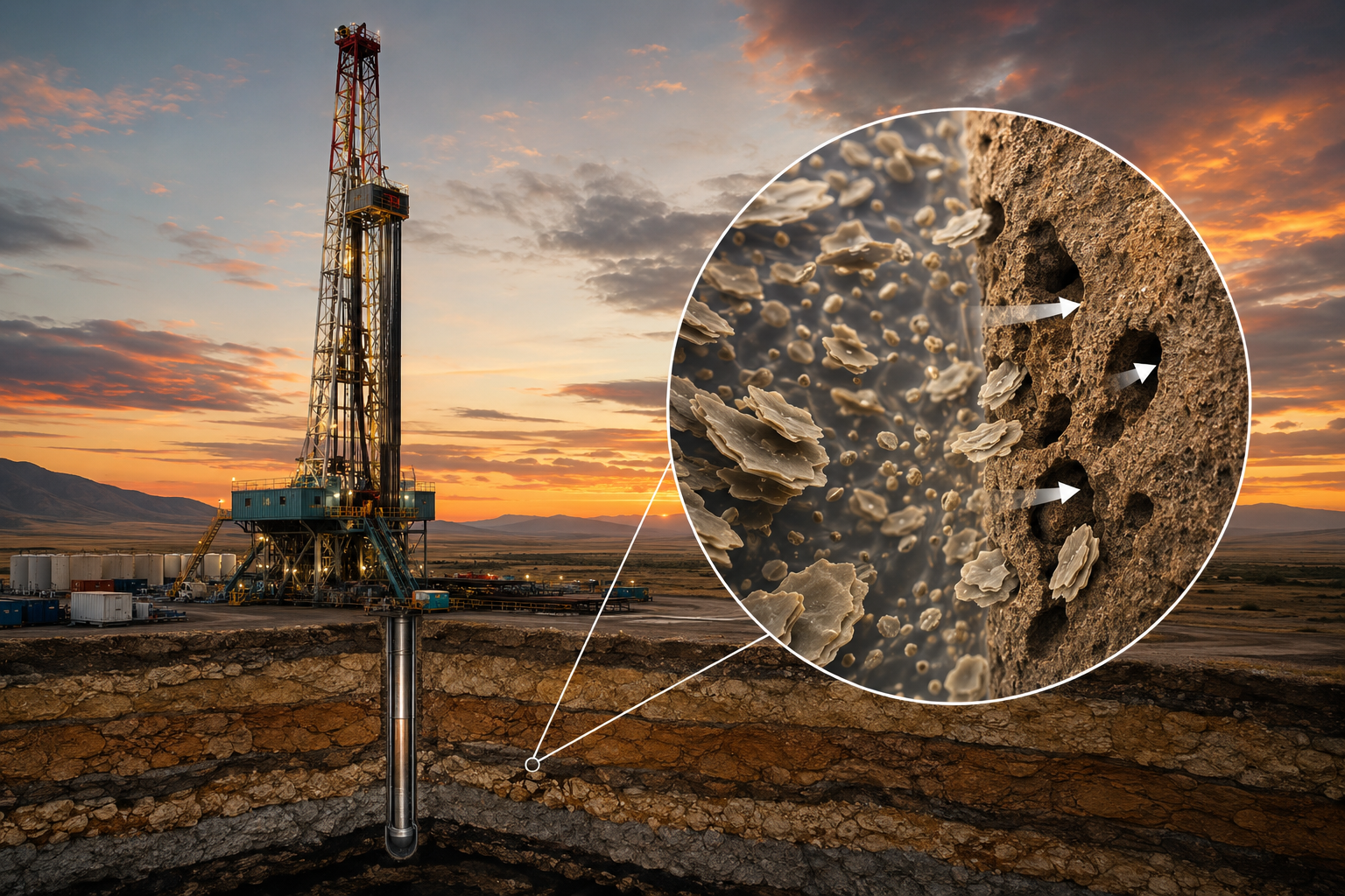
Deep subterranean drilling exposes operations to immense pressures, temperature swings, and fragile formations. If your drilling fluid fails to suspend heavy cuttings or build an impermeable filter cake along the wellbore wall, non-productive time (NPT) climbs rapidly. Pipe sticking, bit balling, and total formation collapse cost operators millions annually.
Sodium bentonite acts as the structural foundation of water-based drilling muds (WBM). Rich in sodium montmorillonite, this natural clay swells up to 15 to 18 times its dry volume when hydrated in fresh water. It creates a high-yield thixotropic gel that coats the wellbore wall, suspends high-density weighting materials like barite, and maintains tight fluid loss control.
By building an ultra-thin, low-permeability filter cake, high-grade sodium bentonite balances hydrostatic pressure against formation pore pressure, locking fragile shales in place and keeping drilling operations running smoothly.
To understand why sodium bentonite dominates water-based drilling muds, look at its crystal structure. Montmorillonite belongs to the smectite clay family, featuring an aluminum octahedral sheet sandwiched between two silicon tetrahedral sheets (a 2:1 layer structure).
When dry, these micro-thin clay platelets stack tightly together, held by electrostatic charges and interlayer cations. The decisive factor lies in which cation sits between those layers.
+-----------------------------------------------------------------------+
| SODIUM vs. CALCIUM MONTMORILLONITE | +-----------------------------------------------------------------------+
| |
| SODIUM BENTONITE (High Swelling) CALCIUM BENTONITE (Low Swelling)|
| |
| +-----------------------+ +-----------------------+ |
| | Silica Sheet | | Silica Sheet | |
| +-----------------------+ +-----------------------+ |
| Na+ Na+ Na+ Ca2+ Ca2+ |
| +-----------------------+ +-----------------------+ |
| | Silica Sheet | | Silica Sheet | |
| +-----------------------+ +-----------------------+ |
| | | |
| [Water Inrush] [Water Inrush] |
| v v |
| Platelets separate completely Platelets remain bound |
| (Swells up to 18x volume) (Swells only 2x-4x volume) | +-----------------------------------------------------------------------+
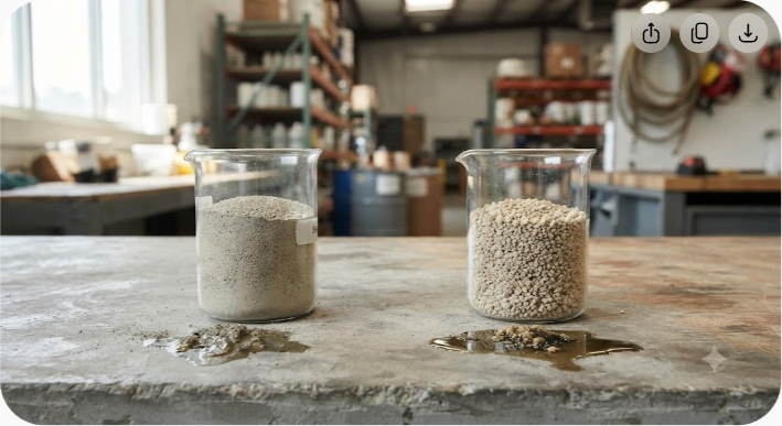
Sodium ions (Na?) carry a single positive charge and a large hydrated ionic radius. When water enters the clay matrix, Na? ions attract water molecules deep between the silicate sheets. This osmotic force pushes the platelets far apart, causing the crystalline structure to expand dramatically and break into microscopic, ribbon-like platelets.
Conversely, calcium ions (Ca²?) carry a double positive charge. They bind the silicate layers tightly together like strong rivets. When exposed to water, calcium bentonite swells only 2 to 4 times its dry volume. It creates a coarse suspension with negligible gel strength, making untreated calcium bentonite unsuitable for primary drilling muds.
When raw sodium bentonite mixes with fresh water, it undergoes a two-step process:
This broad surface area—often exceeding 700 to 800 square meters per gram—enables sodium bentonite to structure water, increase viscosity, and deliver rapid yield strength at lower concentrations.
Drilling fluids must accomplish two contradictory tasks: flow smoothly like water when pumped through high-speed drill bits, yet firm up into a thick gel the second pumps shut down. Sodium bentonite makes this dynamic behavior possible.
[HIGH SHEAR RATE] [ZERO SHEAR / REST] (Pumping through Drill Pipe) (Pumps Turned Off)
+-------------------------+ +-------------------------+
| --- --- --- --- | | | | _|_ | | _|_ |
| --- --- --- --- | =====> | -|- - | -|- - | -|- - |
| --- --- --- --- | | | | _|_ | | _|_ | +-------------------------+ +-------------------------+ Platelets align in rows; Platelets interlock into Viscosity drops (Easy Flow). House-of-Cards Gel Structure (Suspends Heavy Cuttings).
Sodium bentonite suspensions exhibit true thixotropic behavior. The negatively charged flat surfaces of the clay platelets and their positively charged edges create a weak, reversible chemical bond.
When the mud rests, these particles align edge-to-face, forming a rigid, three-dimensional "house-of-cards" network. This static gel strength prevents dense rock cuttings and heavy weighting additives like barite (4.2+ specific gravity) from settling to the bottom of the wellbore during connections or maintenance pauses.
When fluid circulation resumes, shear forces break these delicate inter-particle bonds. The house-of-cards structure collapses, aligning the suspended platelets parallel to the fluid flow path. Viscosity drops instantly, reducing pump pressure requirements and minimizing wear on surface equipment.
In drilling hydraulics, managing the balance between Yield Point (YP) and Plastic Viscosity (PV) determines how effectively a fluid cleans the hole without overloading pump discharge pressures:
High-purity sodium bentonite provides an exceptional YP boost relative to its contribution to PV, giving mud engineers precise control over shear-thinning characteristics.
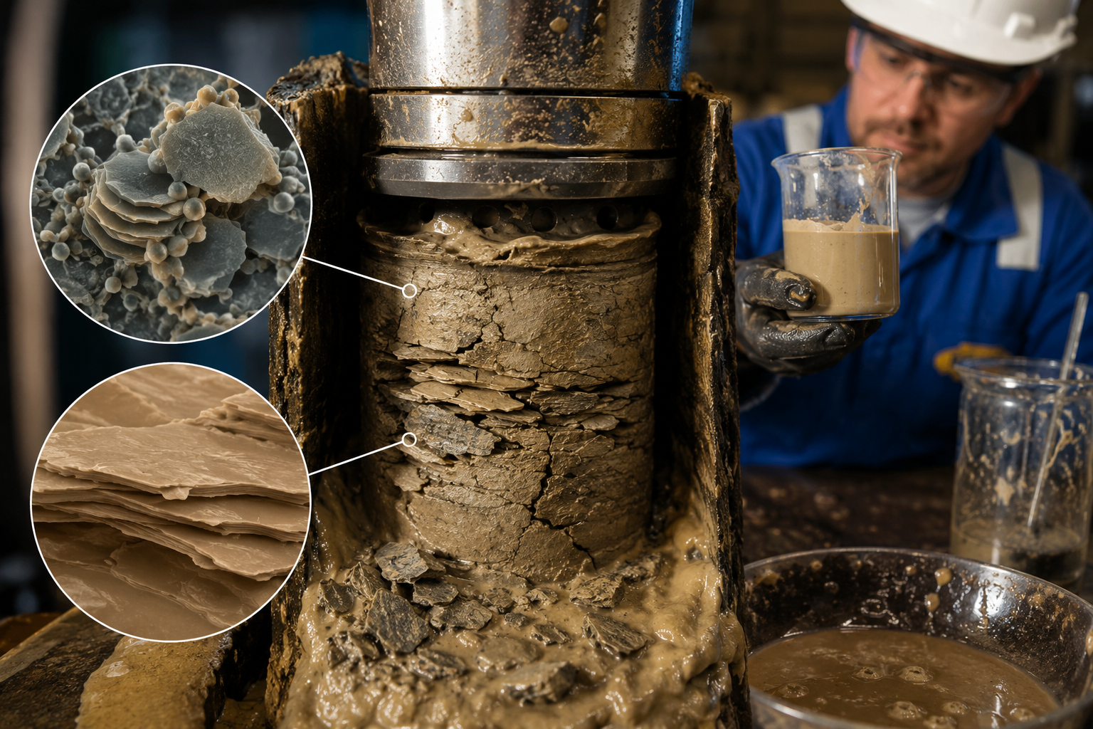
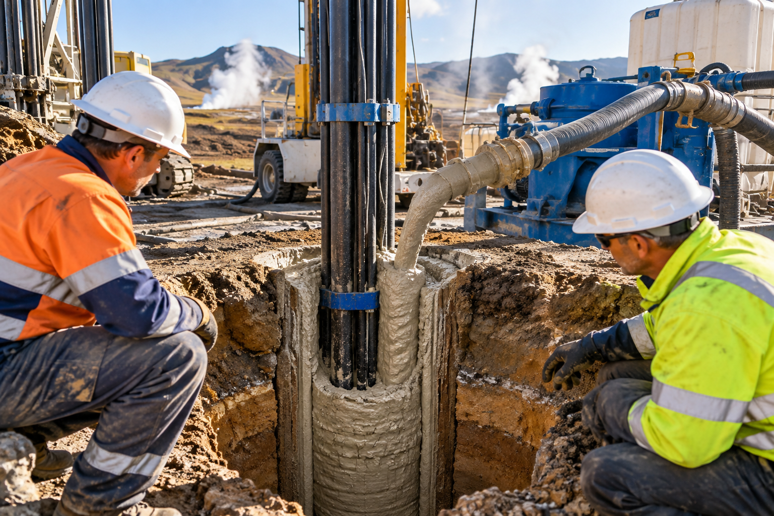
Wellbore instability accounts for a major portion of drilling troubles worldwide. Unstable formations lead to tight holes, reaming, stuck pipe assemblies, and lost circulation zones. Sodium bentonite tackles these risks through three coordinated physical mechanisms.
+-------------------------------------------------------------------------+
| MECHANISMS OF WELLBORE STABILIZATION | +-------------------------------------------------------------------------+
| |
| 1. IMPERMEABLE FILTER CAKE BUILDUP |
| [Wellbore] | Filter Cake (Thin & Tough) | Formation Wall |
| | [===== Clay Platelets =====| High Permeability Sand |
| Fluid | [==========================| Pore Throats Sealed |
| | | |
| 2. HYDROSTATIC PRESSURE MANAGEMENT |
| Mud Column Pressure (Phyd) > Formation Pore Pressure (Ppore) |
| Prevents fluids from kicking and rock faces from sloughing. |
| |
| 3. OSMOTIC & SHALE HYDRATION CONTROL |
| Seals micro-fractures, preventing filtrate water from invading |
| reactive clays and causing swell-induced wellbore collapse. |
| | +-------------------------------------------------------------------------+
When drilling through permeable sandstones or fractured limestones, the liquid portion of the mud (filtrate) tries to escape into the formation due to differential pressure.
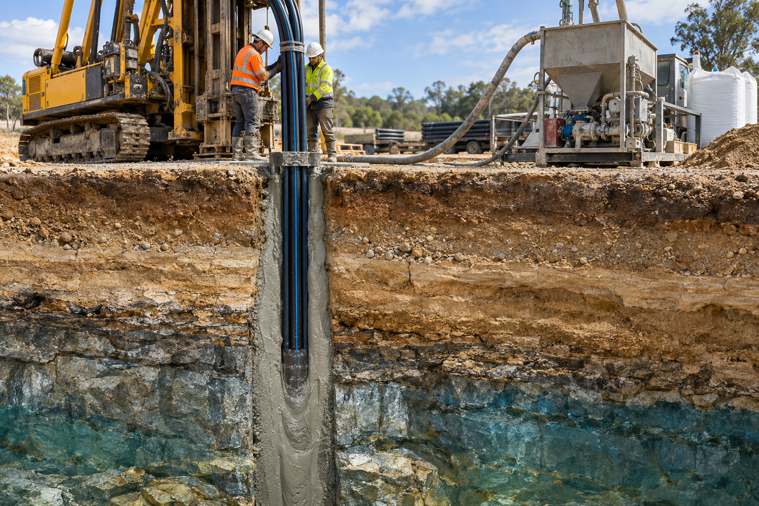
As water passes through small pores, sodium bentonite platelets lay down flat against the open rock wall. Overlapping like tiny scales, these micron-sized sheets form a thin, tough, flexible filter cake.
An optimized sodium bentonite system keeps cake thickness under 2/32 inches (1.6 mm) while reducing standard API fluid loss to under 10 mL/30 min. A thin, low-permeability cake protects production zones from deep filtrate invasion and prevents drill collars from getting differential-stuck against the wall.
To prevent influxes of oil, gas, or formation water (kicks), the mud column's hydrostatic pressure (P_hyd) must exceed formation pore pressure (P_pore). The calculation for hydrostatic pressure is:
Sodium bentonite provides the baseline density and structural suspension capacity needed to keep weighting materials evenly distributed throughout thousands of feet of pipe, ensuring stable, uniform pressure top to bottom.
Reactive shales contain sensitive clays that absorb water quickly. Uncontrolled water invasion causes shales to swell, crack, and slough into the wellbore, leading to stuck drill strings.
By laying down an immediate, low-permeability seal on exposed shale faces, sodium bentonite restricts water movement into the formation matrix. Paired with secondary shale inhibitors like potassium chloride (KCl) or glycol, it provides reliable protection through troublesome mudstone sequences.
To unleash full swelling capacity and achieve targeted viscosity, field crews must handle and hydrate sodium bentonite correctly. Mixing raw bentonite too quickly or using hard water ruins performance before the fluid ever reaches the drill bit.
+-------------------------------------------------------------------------+
| DRILLING MUD MIXING PIPELINE | +-------------------------------------------------------------------------+
| |
| [ Step 1: Water Pre-Treatment ] |
| * Test Hardness (<100 ppm Ca2+) & pH (Adjust to 8.5–9.5 with Soda Ash)|
| | |
| v |
| [ Step 2: Controlled Addition ] |
| * Add Sodium Bentonite slowly through Venturi Hopper (20-30 lbs/bbl) |
| | |
| v |
| [ Step 3: High-Shear Hydration ] |
| * Agitate for 45-60 mins to yield fully dispersed platelets |
| | |
| v |
| [ Step 4: Polymer & Chemical Additives ] |
| * Add PAC, PHPA, or Barite AFTER full clay hydration |
| | |
| v |
| [ Step 5: Quality Assurance Testing ] |
| * Run Marsh Funnel, Rheometer, & API Filter Press checks |
| | +-------------------------------------------------------------------------+
Never dump sodium bentonite directly into raw makeup water. Dissolved calcium (Ca²?) and magnesium (Mg²?) ions suppress clay hydration through ion-exchange reactions.
Add sodium bentonite slowly through a Venturi mixing hopper to prevent dry clumping ("fish-eyes"). Fish-eyes happen when water wets the outside of a clay clump, forming a gel layer that locks the inside dry.
Mechanical shear breaks up clay aggregates into single, active platelets.
If your fluid system requires secondary polymers—such as Polyanionic Cellulose (PAC) for additional fluid loss control or Partially Hydrolyzed Polyacrylamide (PHPA) for shale encapsulation—add them after the bentonite has fully hydrated.
Adding polymers too early coats dry clay particles, blocking water absorption and reducing total hydration efficiency.
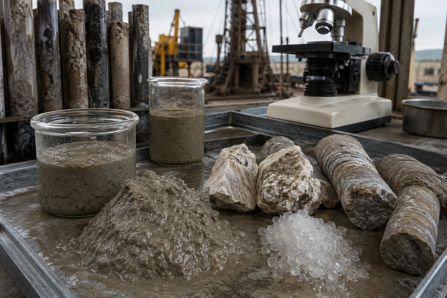
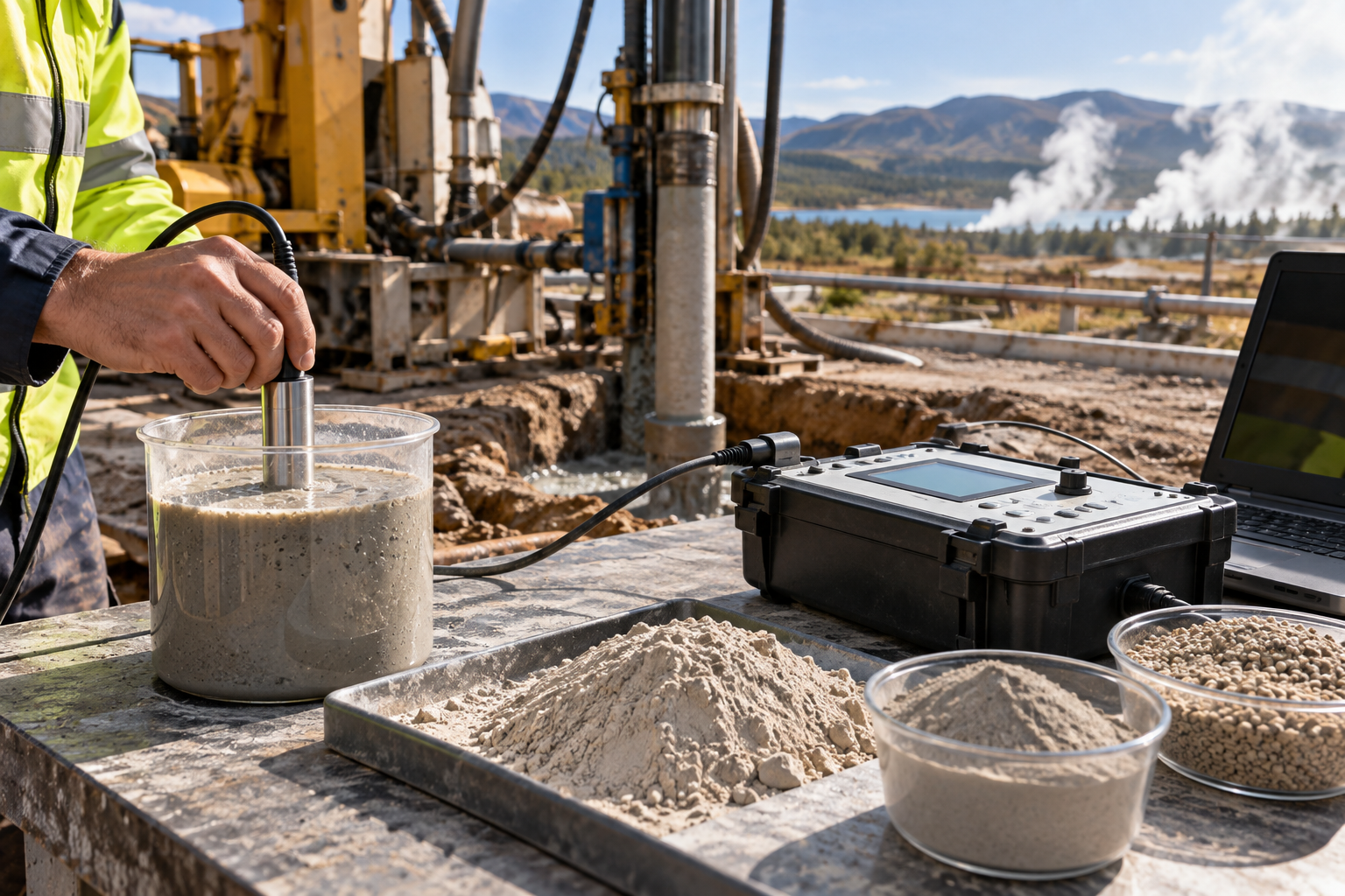
Before launching downhole circulation, run standard field checks on fluid properties:
Selecting the right drilling fluid requires weighing performance demands against cost, environmental impact, and logistics. Below is how high-grade sodium bentonite compares with key alternative systems.
| Operational Property | Premium Sodium Bentonite (WBM) | Untreated Calcium Bentonite | Polymer-Based Fluids (Synthetic) | Oil-Based Muds (OBM / SBM) |
|---|---|---|---|---|
| Swelling Capacity | High (15×–18× volume) | Low (2×–4× volume) | None (Chemical Viscosity) | N/A (Non-aqueous) |
| Gel Strength & Suspension | Excellent (Thixotropic) | Poor | Fair to Moderate | Superior |
| Fluid Loss Control | Excellent (Thin filter cake) | Poor | Good (Requires PAC/CMC) | Outstanding |
| Temperature Limit | Up to 300°F (149°C) | Up to 200°F (93°C) | 250°F–325°F (121°C–163°C) | 400°F+ (204°C+) |
| Environmental Impact | Eco-friendly / Non-toxic | Eco-friendly / Non-toxic | Biodegradable varieties | High disposal regulations |
| Cost Profile | Low to Moderate | Very Low | Moderate to High | High initial investment |
| Salt Tolerances | Sensitivities above 10,000 ppm NaCl | Moderate | High | Excellent |
While oil-based muds (OBM) perform exceptionally well in high-temperature wells, their strict environmental regulations, high chemical costs, and difficult disposal requirements make sodium bentonite WBMs the preferred, cost-effective choice for many onshore and shallow offshore wells.
No drilling application runs smoothly forever. Changing geology and unexpected inflows present challenges that require quick fluid adjustments.
+-------------------------------------------------------------------------+
| DOWNHOLE MUD CONTAMINATION & FIXES | +-------------------------------------------------------------------------+
| |
| CONTAMINANT: Salt Water Influx (NaCl > 10,000 ppm) |
| EFFECT: Forces clay platelets to flocculate, spiking fluid loss. |
| SOLUTION: Pre-treat with CMC/PAC polymers, or convert to salt-tolerant |
| clay blends like Attapulgite. |
| |
| CONTAMINANT: Anhydrite / Gypsum (Ca2+ Contamination) |
| EFFECT: Replaces Na+ ions with Ca2+, collapsing yield strength. |
| SOLUTION: Treat with Soda Ash or Sodium Acid Pyrophosphate (SAPP). |
| |
| CONTAMINANT: High Thermal Stress (>300°F / 149°C) |
| EFFECT: Flattens gel structure, leading to severe fluid loss. |
| SOLUTION: Blend lignite, synthetic thinners, or thermal stabilizers. |
| | +-------------------------------------------------------------------------+
When a well strikes a saltwater zone, high salt concentrations (NaCl > 10,000 ppm) compress the electrical double layer around individual clay particles. Deprived of repulsive charges, platelets clump together into large, irregular clusters in a process known as flocculation.
Flocculation causes rheology spikes followed by a total loss of gel structure, allowing solids to drop and fluid loss to surge.
Drilling through anhydrite or gypsum (CaSO?) formations floods the mud system with Ca²? ions. Calcium quickly swaps places with sodium ions on the clay lattice, converting high-swelling sodium bentonite into low-yielding calcium bentonite.
At bottom-hole temperatures above 300°F (149°C), water molecules begin to break away from hydrated clay platelets. Deprived of bound water layer protection, bentonite slurries experience thermal flocculation, resulting in high gel strength and uncontrollable fluid loss.
To ensure consistent downhole performance, global exploration companies rely on standard quality specifications for bulk bentonite purchases.
+-----------------------------------------------------------------------+
| API SPECIFICATION 13A REQUIREMENTS | +-----------------------------------------------------------------------+
| |
| [ PARAMETER ] [ ACCEPTABLE TARGET ] |
| |
| Viscometer Reading @ 600 RPM -----> 30 Minimum |
| Yield Point / Plastic Viscosity -----> 3.0 Maximum Ratio |
| Filtrate Loss (30 min @ 100 psi) --> 12.5 mL Maximum |
| Wet Residue (>75 microns / 200 Mesh) 4.0% Maximum |
| | +-----------------------------------------------------------------------+
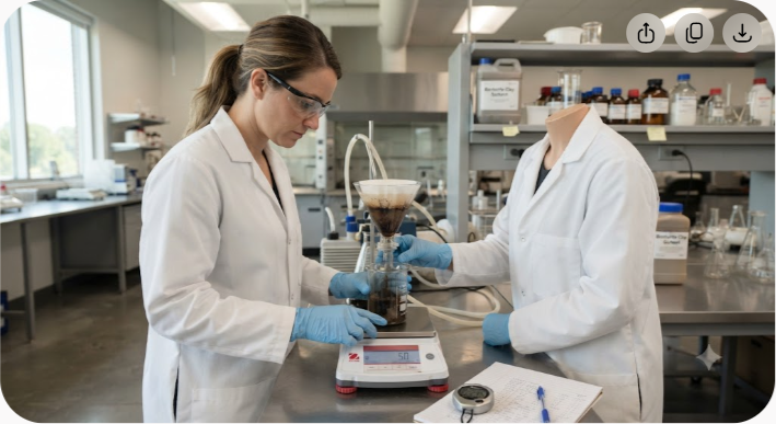
The standard benchmark for drilling-grade bentonite is API Specification 13A (Section 4 for Untreated Bentonite, Section 5 for OCMA-grade). Key requirements include:
Meeting these baseline metrics ensures the clay will yield predictable viscosity and filtration control without clogging drill bits or surface mud pumps with abrasive grit.
Not all sodium bentonite deposits offer equal performance. Many global reserves contain low-grade calcium bentonite modified with synthetic polymers to pass short-term API tests. These chemically enhanced clays often lose viscosity when subjected to high shear forces or moderate heat downhole.
Sourcing high-yield, naturally occurring sodium bentonite ensures durable long-term stability downhole. Global mining hubs with high-grade natural reserves—such as India's Kutch basin—provide stable, high-montmorillonite clay reserves to energy markets across North America, the Middle East, and Southeast Asia.
With over 60 million tons of natural reserves, producers like Axewelledge supply certified API 13A sodium bentonite to international drilling operations, ensuring long-term supply stability for high-volume programs.
An onshore drilling operator in an alluvial river basin encountered severe wellbore instability while drilling through a 1,200-foot section of unconsolidated sand and gravel.
Using a low-cost, polymer-only mud system, the team experienced severe fluid loss (28 mL/30 min), leading to differential sticking, washouts exceeding 35% over bit size, and multiple reaming runs that added 48 hours of non-productive time.
+-----------------------------------------------------------------------+
| CASE STUDY: FIELD PERFORMANCE SHIFT | +-----------------------------------------------------------------------+
| |
| METRIC BEFORE (Polymer) AFTER (Na-Bentonite) |
|---|
| API Fluid Loss (mL) 28 mL 6.2 mL |
| Filter Cake Thickness 4/32 in (Thick/Soft) 1.5/32 in (Tough) |
| Average Washout Rate 38% < 5% |
| Non-Productive Time (NPT) 48 Hours 0 Hours |
| Overall ROP (ft/hr) 32 ft/hr 58 ft/hr |
The fluid engineering team replaced the polymer fluid with a pre-hydrated API 13A sodium bentonite system (25 ppb loading) treated with 0.5 ppb soda ash and a low concentration of PAC polymer.
Using premium sodium bentonite is one of the most effective ways to lower total well delivery costs. While low-grade clays or quick chemical fixes might seem cheaper initially, they often lead to high chemical treatment bills, premature bit wear, and costly downhole delays.
By building an impermeable filter cake, controlling fluid loss, and maintaining ideal fluid rheology under varying conditions, natural sodium bentonite keeps wells stable and running efficiently from spud to total depth.
To ensure your drilling mud performs reliably under tough formation conditions, partner with global producers like Axewelledge for consistent, API-certified sodium bentonite supply tailored to your well design.

Have questions about our products? We're here to help!