Axewelledge, a leading exporter from India, specializes in high-quality Bentonite. With a commitment to excellence, we supply premium Bentonite to the Middle East and Southeast Asia markets.


North Angle Complex, 304,
150 Feet Ring Rd, Opposite Ambedkar Nagar BRTS Stop,
Madhav Park, Punit Nagar,
Mavdi, Rajkot, Gujarat 360004
© Axewelledge 2026, All Rights Reserved.
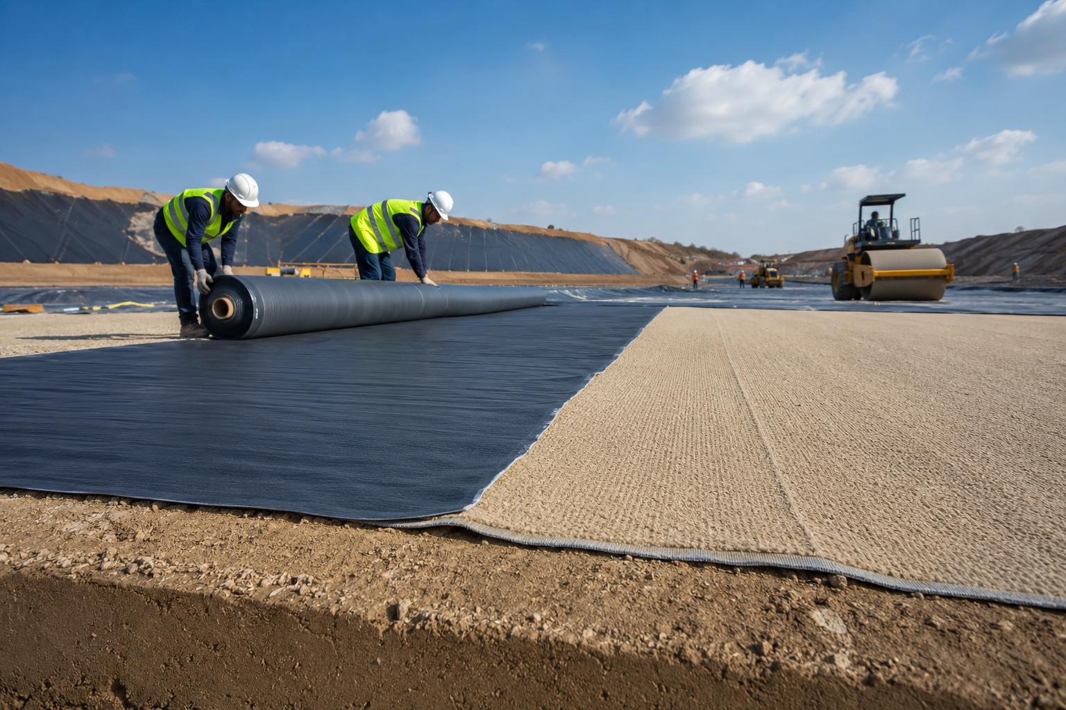
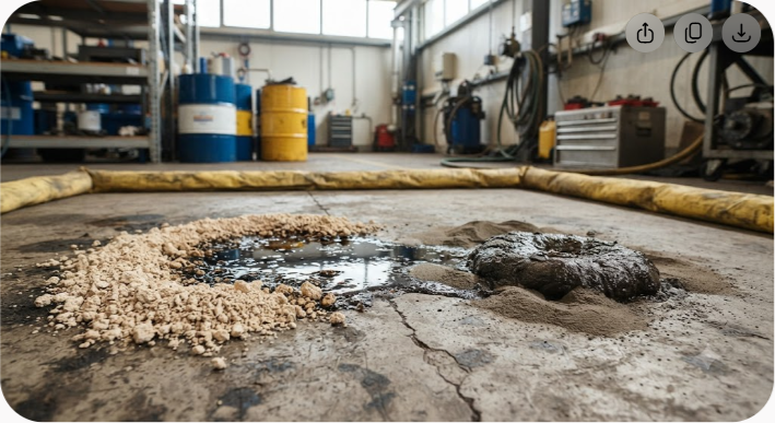
When toxic leachate escapes a landfill, it does not just moisten the subsoil—it migrates directly into regional aquifers, poisoning drinking water for generations. Standard synthetic plastic membranes offer high tensile strength, but a single puncture during gravel placement or a tiny tear along a field weld ruins the entire containment system.
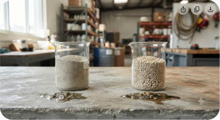
That is why geoenvironmental engineers rely on high-swelling sodium bentonite clay. When hydration occurs, sodium bentonite expands up to 15 to 18 times its dry volume, transforming into a dense, low-permeability gel layer. This natural barrier drops hydraulic conductivity below 1×10?? cm/s, easily satisfying strict international environmental standards while providing a crucial advantage synthetic sheets lack: natural self-healing capabilities.
If a rock presses into a bentonite layer or the subgrade shifts, the clay swells into the void and re-seals the break automatically. Below, we break down the engineering mechanics, design parameters, installation standards, and long-term economic advantages of using sodium bentonite clay for landfill liners and groundwater isolation.
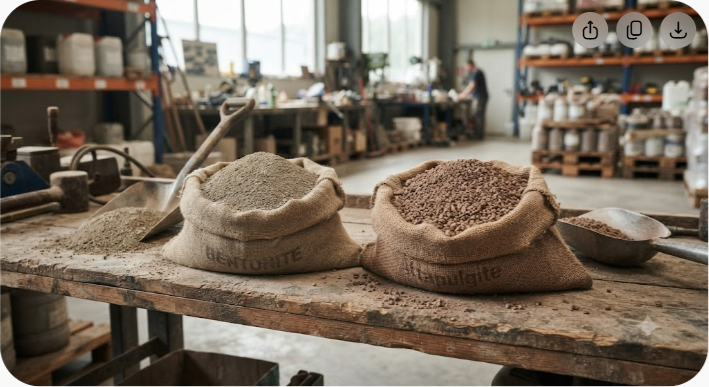
Bentonite is a smectite-rich clay mineral formed primarily from weathered volcanic ash. Its active mineral component, montmorillonite, gives the clay its unique colloidal and hydraulic properties.
+-------------------------------------------------------------+
| Montmorillonite Clay Structure |
| +-----------------------------------------------------+ |
| | Silica Tetrahedral Sheet | |
| +-----------------------------------------------------+ |
| | Alumina Octahedral Sheet | |
| +-----------------------------------------------------+ |
| | Silica Tetrahedral Sheet | |
| +-----------------------------------------------------+ |
| [ Exchangeable Sodium Ions (Na+) & Water ] |
| +-----------------------------------------------------+ |
| | Silica Tetrahedral Sheet | |
| +-----------------------------------------------------+ | +-------------------------------------------------------------+
The crystalline lattice consists of microscopic three-layer sheets: an octahedral sheet containing aluminum and magnesium sandwiched between two tetrahedral silica sheets. Because of naturally occurring ionic substitutions within this lattice, the sheets carry a net negative surface charge. Exchangeable cations, predominantly sodium (Na?) or calcium (Ca²?), hold these platelets together.
Not all bentonite performs equally when liquid enters the equation. The dominant cation determines whether the material works as an effective environmental barrier:
In geoenvironmental containment design, the key benchmark is Darcy's Law, which defines fluid flow through porous media:
Where Q represents flow rate, k is the hydraulic conductivity (permeability coefficient), i is the hydraulic gradient, and A is the cross-sectional flow area.
To prevent hazardous leachate migration, regulatory frameworks require bottom liners to achieve a hydraulic conductivity (k) of 1×10?? cm/s or lower. High-grade sodium bentonite easily surpasses this standard, often hitting 1×10?¹? to 1×10?¹¹ cm/s under light confining pressure. At these rates, fluid movement through a 30 cm compacted bentonite-soil layer drops to fractions of a millimeter per year—effectively stopping liquid transport.
Engineers specify sodium bentonite across critical environmental containment structures where structural failure is not an option.
============================================================= Leachate Layer ------------------------------------------------------------- Geotextile Filter Cushion ::::::::::::::::::::::::::::::::::::::::::::::::::::::::::::: Geonet / Drainage Layer ============================================================= HDPE Geomembrane (1.5 - 2.0 mm) ############################################################# Geosynthetic Clay Liner (GCL) ............................................................. Compacted Bentonite-Soil Layer ------------------------------------------------------------- Prepared Subgrade
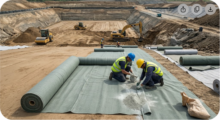
Modern municipal solid waste (MSW) and industrial hazard landfills use multi-layer composite liner configurations. A flexible synthetic membrane (such as 2.0 mm high-density polyethylene, or HDPE) lies directly over a hydrated bentonite layer or Geosynthetic Clay Liner (GCL).
This setup leverages complementary physical properties: the plastic membrane blocks diffusive liquid transport, while the underlying bentonite blocks advective leakage through pinholes, installation punctures, or seam defects in the plastic.
When a landfill reaches operational capacity, closing the facility requires an impermeable top cap to block rainwater infiltration. Preventing rainwater from soaking into the buried waste stops ongoing leachate generation. Bentonite caps withstand differential settlement as waste decomposes underneath without cracking, maintaining their seal long after rigid barriers fail.
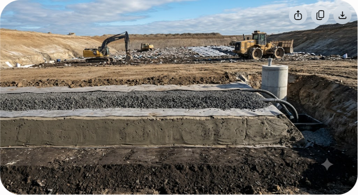
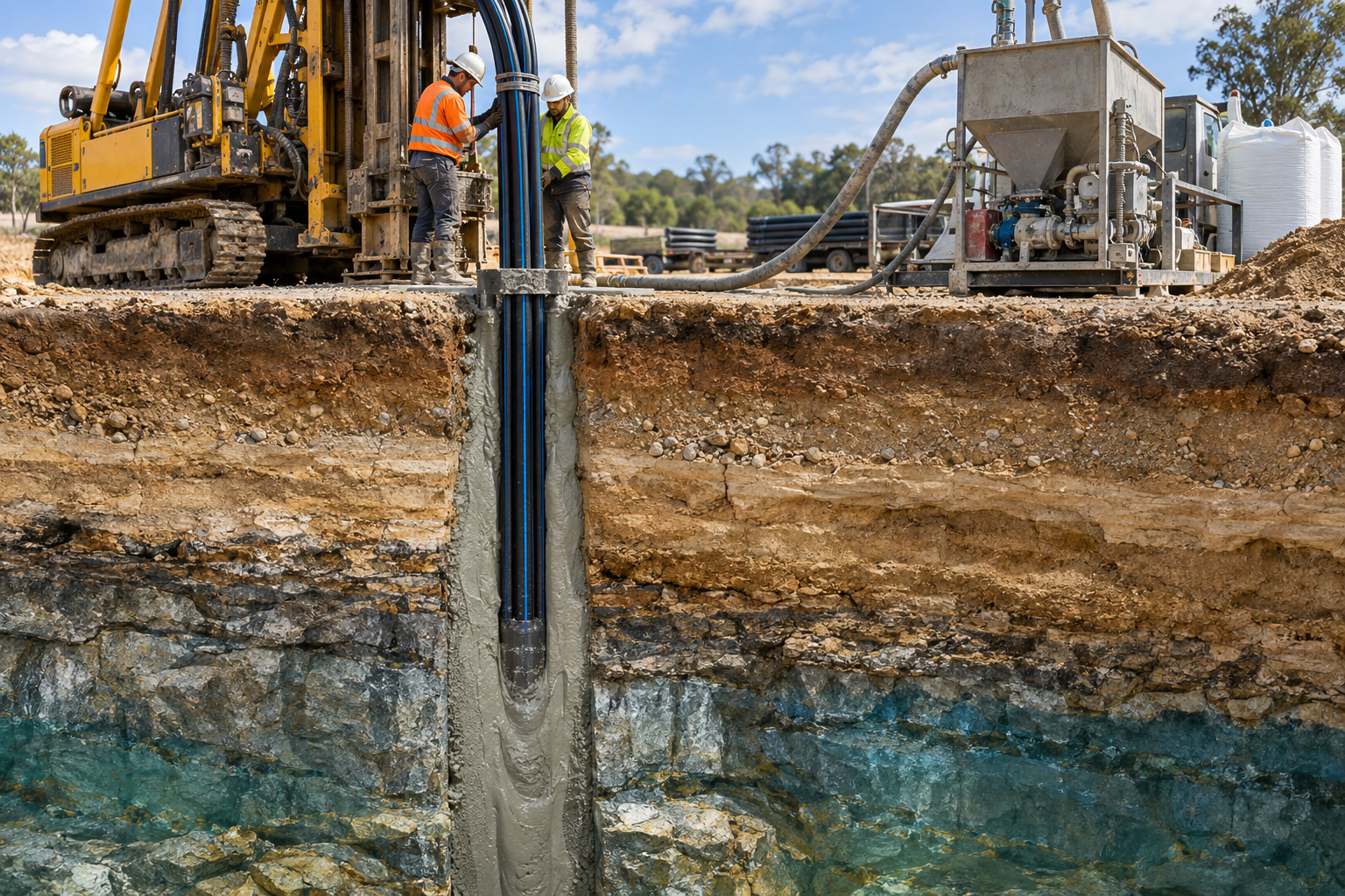
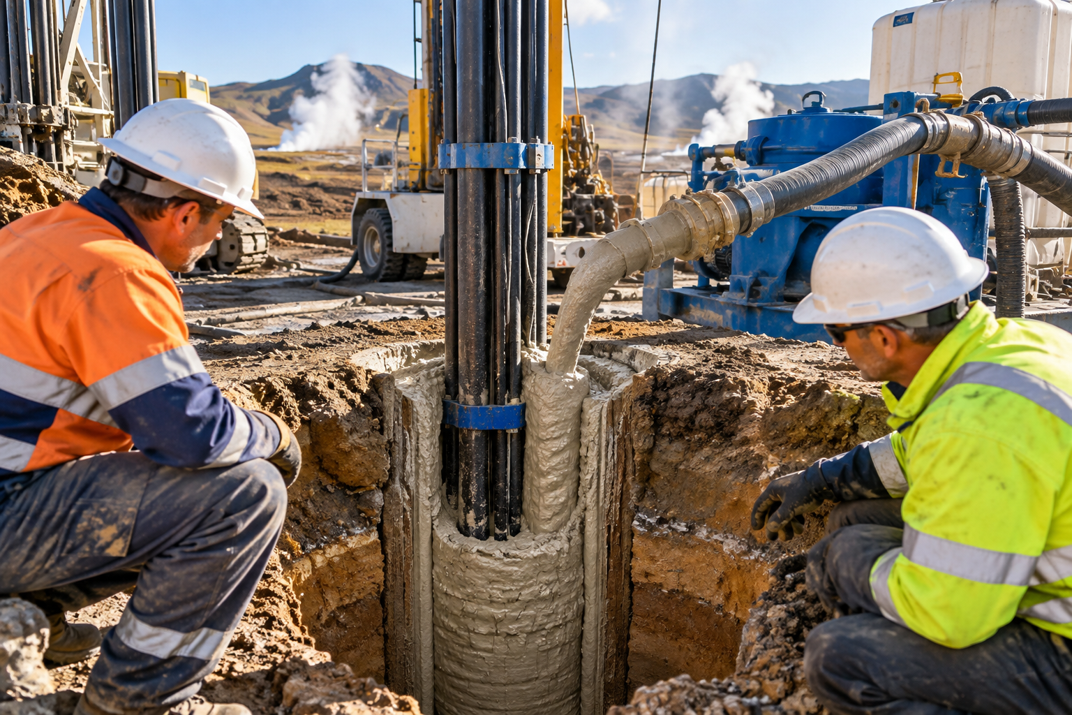
To contain existing contaminated groundwater plumes near industrial sites, engineers excavate narrow trenches around the site perimeter down to an impermeable bedrock layer. Filling these trenches with a sodium bentonite, cement, and soil slurry forms a permanent vertical barrier wall that redirects subsurface groundwater around the site.
Mining operations and chemical plants generate billions of liters of process wastewater containing heavy metals, salts, and acids. Lining these holding ponds with compacted sodium bentonite prevents toxic runoff from entering regional watersheds.
Civil engineers choose between two primary methods when integrating bentonite into hydraulic barriers: bulk Compacted Clay Liners (CCL) or manufactured Geosynthetic Clay Liners (GCL). Both options offer distinct technical and economic advantages depending on site conditions.
| Feature / Metric | Compacted Clay Liner (CCL) | Geosynthetic Clay Liner (GCL) |
|---|---|---|
| Typical Thickness | 60 cm to 90 cm (24 to 36 inches) | 0.5 cm to 1.0 cm (0.2 to 0.4 inches) |
| Material Composition | Native soil blended with 5%–15% bentonite | Pure sodium bentonite sandwiched between geotextiles |
| Hydraulic Conductivity (k) | 1×10?? to 1×10?? cm/s | 1×10?? to 1×10?¹¹ cm/s |
| Installation Speed | Slow (requires multi-pass compaction) | Fast (rolled out directly in panels) |
| Airspace Consumption | High (occupies significant landfill volume) | Minimal (maximizes waste storage volume) |
| Sensitivity to Subgrade Settlement | Vulnerable to shear cracking if settlement is uneven | Highly flexible; geotextile reinforcement retains integrity |
| Quality Control (QC) | Field-dependent (requires density & moisture testing) | Factory-controlled manufacturing standards |
| Self-Healing Ability | Moderate | High (dense bentonite layer expands rapidly) |
A design is only as reliable as its field installation. Poor subgrade preparation or incorrect hydration destroys the sealing capacity of high-grade bentonite. Follow this step-by-step workflow to ensure long-term hydraulic performance.
+--------------------+ +--------------------+ +--------------------+
| 1. Subgrade Prep | ---> | 2. Material Prep | ---> | 3. Placement & |
| Clear rocks >25mm | | Control moisture | | Overlap Panels |
| Proof-roll soil | | Verify clay grade | | Min 300mm seams | +--------------------+ +--------------------+ +--------------------+ | +--------------------+ +--------------------+ | | 5. Cover & Protect | <--- | 4. Seam Powdering | <-----------+
| Min 300mm soil cap | | Apply dry sodium |
| Place immediately | | bentonite at joints| +--------------------+ +--------------------+
Transitioning from fully synthetic or chemically modified barriers to high-grade natural sodium bentonite offers long-term environmental and financial benefits.
+-------------------------------------------------------------+
| [Coarse Soil] [Coarse Soil] |
| (Grain) (Grain) |
| |
| ~~~~~~~~ Hydrated Gel ~~~~~~~~ |
| ~ Expanded Sodium Bentonite ~ |
| ~ Fills Interstitial Voids ~ |
| ~~~~~~~~~~~~~~~~~~~~~~~~~~~~~~ |
| |
| [Coarse Soil] [Coarse Soil] |
| (Grain) (Grain) | +-------------------------------------------------------------+ Fluid flow paths sealed; water molecules trapped in electrical double-layers.
Unlike polymer-based geomembranes, which can suffer oxidative degradation, plasticizer leaching, or stress cracking after several decades underground, natural sodium bentonite is an inorganic mineral. It does not decay, rot, or degrade over time. Once installed beneath a soil cover, its hydraulic barrier performance remains stable indefinitely.
Landfill caps in Northern Europe, North America, and high-altitude regions endure severe freeze-thaw cycles. When water inside conventional compacted clay freezes, ice lenses expand, creating structural micro-fissures. When the ice thaws, these fissures leave behind open leak channels.
Sodium bentonite handles freeze-thaw and wet-dry cycles without losing performance. As moisture returns, the clay's high swelling capacity expands the gel back into micro-cracks, completely sealing the matrix. Repeated field tests show zero loss in hydraulic conductivity across hundreds of freeze-thaw cycles.
Landfill airspace directly drives site revenue—every cubic meter consumed by structural liner materials is a cubic meter of lost waste capacity. Replacing a 90 cm (3-foot) conventional compacted clay liner with a 1 cm GCL reclaims roughly 89 cm of depth across the entire footprint. On a typical 20-hectare landfill site, that simple design change reclaims over 170,000 cubic meters of volume, translating into millions of dollars in added waste disposal revenue.
While sodium bentonite is extremely resilient, geoenvironmental engineers must evaluate site-specific chemical compatibility before installation. Toxic leachates can alter the ionic charges that drive swelling.
High concentrations of divalent or trivalent cations (such as Ca²?, Mg²?, or Fe³?) in leachate can replace sodium ions (Na?) on the montmorillonite surface through cation exchange. This process converts high-swelling sodium bentonite into low-swelling calcium bentonite, causing the clay structure to shrink and raising permeability.
High-Swelling Na-Bentonite + Divalent Cations (Ca2+) ---> Collapsed Low-Swelling Ca-Bentonite ---> Increased Micro-Pore Space ---> Higher Permeability
Similarly, hyper-saline liquids compress the electrical double layer surrounding clay particles, reducing swelling volume.
To handle complex aggressive leachates (such as ash monofill runoff or industrial chemical waste), specifying the correct raw mineral grade is critical:
For projects demanding reliable long-term performance, sourcing high-purity sodium bentonite from established global producers ensures consistent mineral quality, high swelling ratios, and minimal non-reactive gangue content.
Large-scale mining and exporting leaders like Axewelledge supply premium sodium bentonite reserves worldwide. Their material offers the precise swelling and sealing capacity required for major environmental containment projects across civil infrastructure, mining, and waste management sectors.
An industrial wastewater plant in Southeast Asia faced strict regulatory mandates to seal a 5-hectare sludge settling basin located over a high-water-table sand aquifer. Local native soils lacked sufficient natural clay content to form a reliable barrier.
Solution: The design team specified an engineered Soil-Bentonite (SB) liner blended with 8% high-purity sodium bentonite.
Result: Post-construction core sampling confirmed a hydraulic conductivity of 2.4×10?¹? cm/s. Perimeter monitoring wells showed zero pollutant migration into adjacent groundwater reserves over five years of continuous tracking.
An arid landfill expansion required a bottom liner that could withstand high thermal swings during installation without drying out or cracking before final capping.
Solution: Engineers deployed a needle-punched Geosynthetic Clay Liner (GCL) paired with an HDPE geomembrane. The factory-controlled GCL allowed rapid installation, cutting field exposure time by 60% compared to traditional compacted clay lifts.
Result: The facility added over 120,000 cubic meters of usable waste capacity while achieving complete hydraulic sealing that met international environmental standards.
Determining the exact amount of sodium bentonite needed to seal a site depends on soil grain size distribution, target permeability, and total coverage area.
To determine total dry bentonite mass (M_b) required:
Where:
Coarse Sand / Gravel Fine Sand Silt with Low Clay (High Permeability) (Moderate Permeability) (Low Permeability) +-------------------+ +-------------------+ +-------------------+
| Add 10% - 15% | | Add 7% - 10% | | Add 3% - 6% |
| Bentonite | | Bentonite | | Bentonite | +-------------------+ +-------------------+ +-------------------+
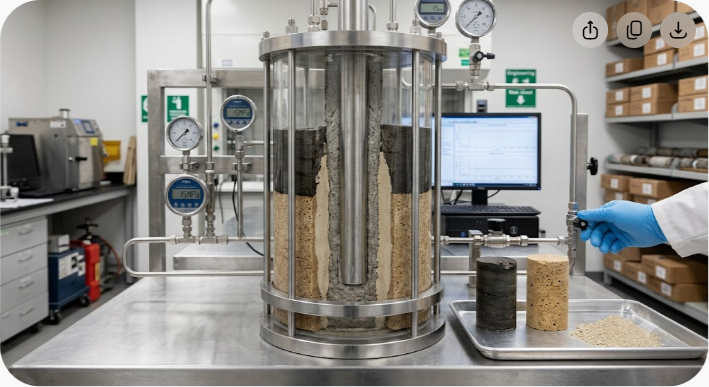
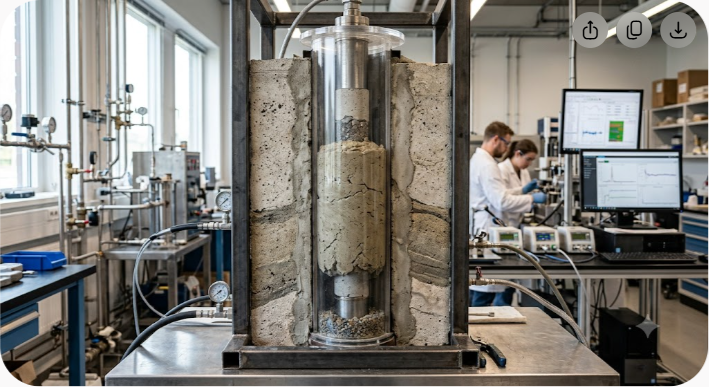
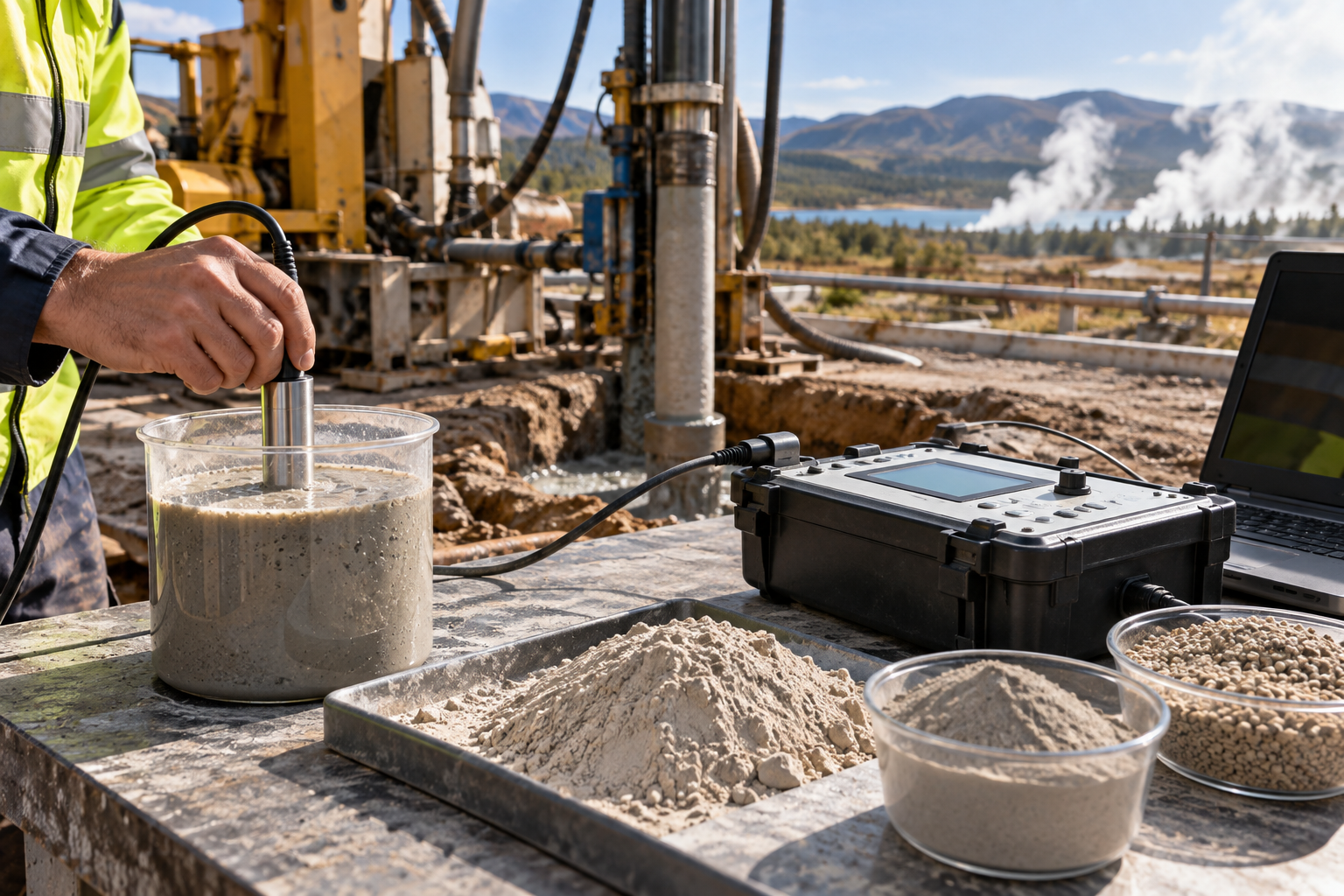
Always verify exact dosage rates through laboratory falling-head permeability testing on actual site soil samples prior to field distribution.
Environmental regulations surrounding leachate control and industrial effluent management continue to tighten worldwide. As civil engineers work to minimize carbon footprints while ensuring absolute containment, natural mineral solutions offer clear advantages over energy-intensive synthetic options.
High-purity sodium bentonite remains unmatched in its ability to self-heal, maintain stability across temperature extremes, and lock down toxic liquids for decades. Sourcing high-grade material ensures your project achieves specified hydraulic conductivity, simplifies site installation, and protects surrounding groundwater ecosystems.
Plan your next environmental containment project with proven mineral solutions. Connect with the engineering and supply experts at Axewelledge to review technical specifications, request high-swelling sodium bentonite samples, and secure dependable mineral supply for your site.


Have questions about our products? We're here to help!