Axewelledge, a leading exporter from India, specializes in high-quality Bentonite. With a commitment to excellence, we supply premium Bentonite to the Middle East and Southeast Asia markets.


North Angle Complex, 304,
150 Feet Ring Rd, Opposite Ambedkar Nagar BRTS Stop,
Madhav Park, Punit Nagar,
Mavdi, Rajkot, Gujarat 360004
© Axewelledge 2026, All Rights Reserved.
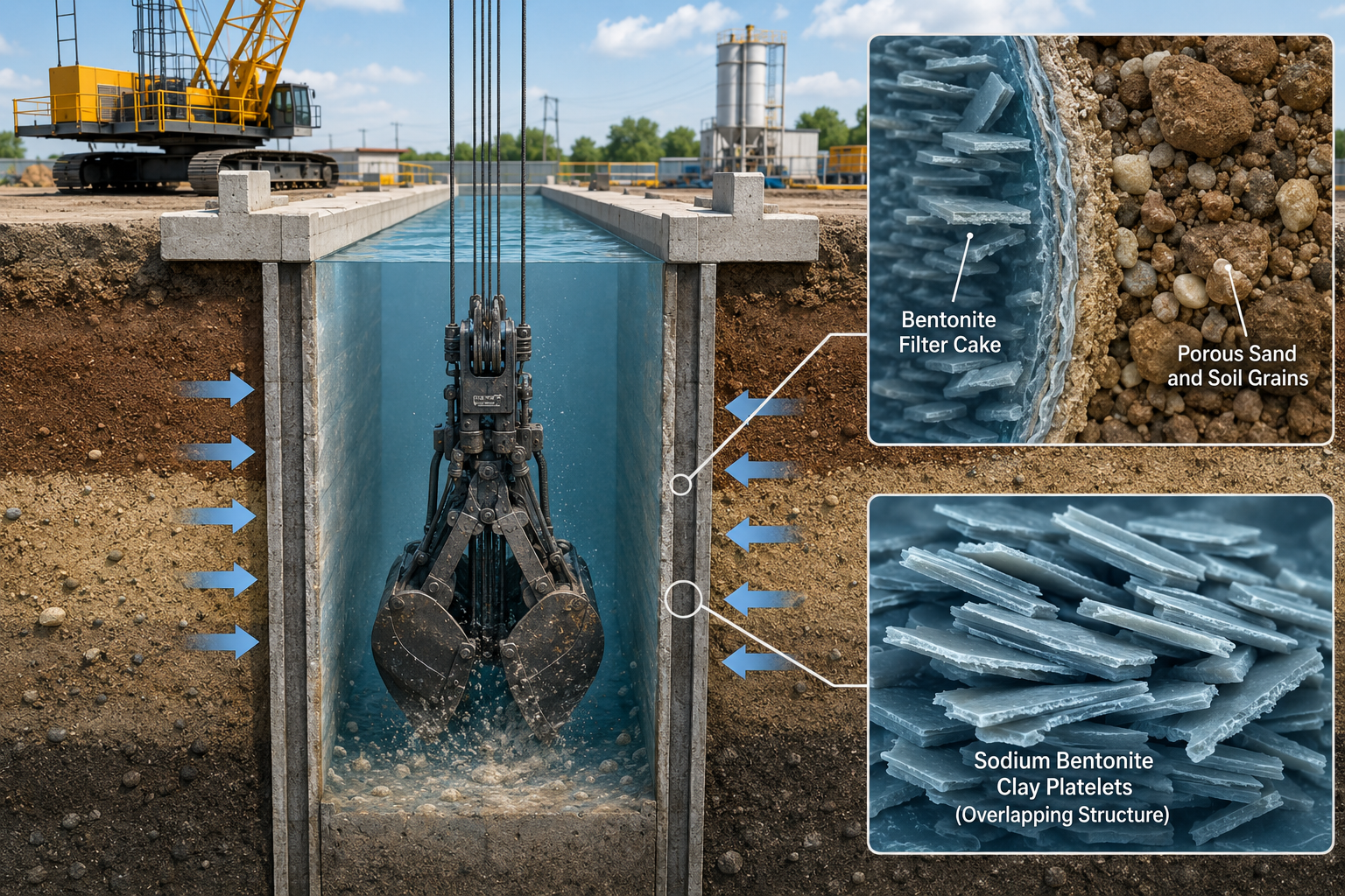
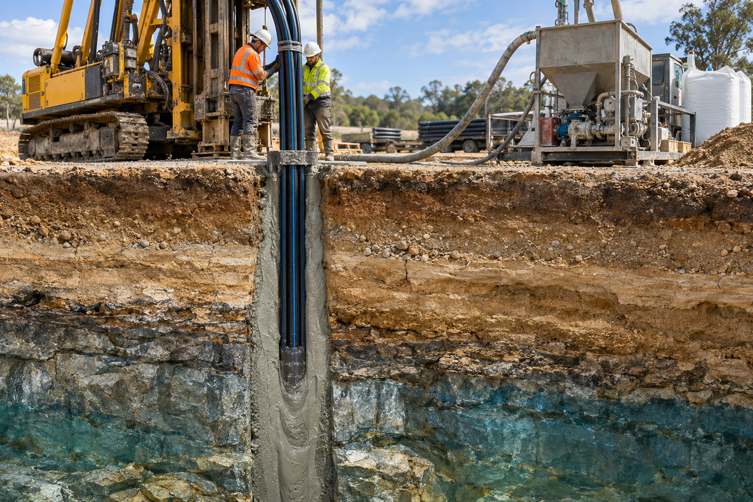
Deep foundation engineering leaves zero room for structural hesitation. When you dig a trench 100 feet deep into unstable, water-saturated ground right next to a historic high-rise, the surrounding soil wants to collapse inward. Bentonite slurry prevents that structural failure. By creating continuous hydrostatic pressure and forming an impermeable, micro-thin membrane called a filter cake against the trench walls, this thixotropic fluid holds thousands of tons of earth in place without mechanical shoring.
Without a properly engineered bentonite slurry, constructing a deep diaphragm wall in urban or coastal environments would be virtually impossible. In this guide, we break down the exact physics of slurry stabilization, how filter cake mechanics work at the particle level, critical mix design parameters, real-world troubleshooting, and best practices for slurry management during concrete placement.
To understand why bentonite slurry works, you first need to look at what happens when you cut a vertical slot into the ground. Soil possesses shear strength derived from friction between grains and cohesion between particles. However, as an excavation deepens, the internal stress within the soil mass exceeds its natural shear resistance.
Two primary forces work relentlessly to collapse an open excavation:
a ?
): The lateral thrust exerted by the soil mass trying to slump forward into the void.
When excavating deep diaphragm wall panels, installing conventional temporary internal bracing or ground anchors is structurally impractical and economically prohibitive. The trench must remain open and completely unobstructed so that massive mechanical grab or hydrofraise (slurry trencher) equipment can operate freely to full depth.
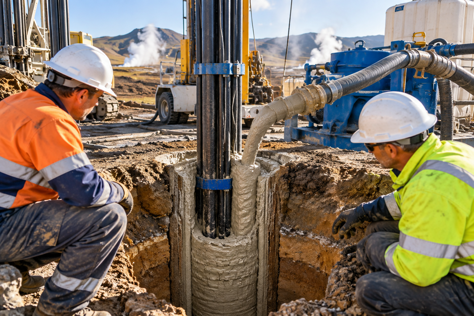
Bentonite slurry solves this challenge by acting as a liquid shore. It exerts an outward hydraulic thrust that offsets both active earth pressure and pore water pressure simultaneously.
$$ P_{ ext{slurry}} = gamma_{ ext{slurry}} imes z $$
Where ? slurry ?
is the unit weight of the slurry mix and z is the depth below the fluid line. Because sodium bentonite slurry can be engineered to a density higher than water (typically 1.03 to 1.15 g/cm 3 , or 64.3 to 71.8 lb/ft 3 ), it generates a net positive hydrostatic pressure against the soil interface, provided the fluid level inside the guide walls is maintained at least 1.5 meters (5 feet) above the surrounding natural groundwater table.
Bentonite slurry is a colloidal suspension of high-purity sodium bentonite clay mixed thoroughly with freshwater. Sodium bentonite is a naturally occurring clay composed primarily of the smectite mineral montmorillonite.
At the molecular level, montmorillonite consists of microscopic, three-layer crystalline sheets: an octahedral alumina sheet sandwiched between two tetrahedral silica sheets. These sheets carry a permanent negative charge on their flat surfaces and weak positive charges along their broken edges.
The chemical layer arrangement consists of an alumina octahedral sheet placed between two silica tetrahedral sheets, separated by hydrated sodium ions (Na + ) and interlayer water molecules.
When dry sodium bentonite meets water, water molecules rush into the interlayer spaces between these sheets. Hydrated sodium ions (Na + ) draw water deep into the crystal structure, causing the clay particles to swell up to 15 to 20 times their dry volume. As these delicate platelets separate and disperse throughout the water column, they form a complex, interconnected continuous gel matrix.
The fundamental key to bentonite performance in excavation engineering is thixotropy. Thixotropy is a time-dependent, non-Newtonian fluid behavior where the material acts as a viscous gel when stationary, but thins down to a fluid state when subjected to mechanical shear stress.
Hydrostatic pressure alone cannot stabilize a porous soil wall. If you filled an open trench in coarse sand with pure water, the liquid would simply drain out through the soil pores into the surrounding ground. Fluid levels would drop, hydrostatic head would collapse, and the trench walls would cave in.
Bentonite slurry prevents fluid migration by building a micro-thin, impermeable barrier directly on the exposed trench face: the filter cake (also known as the filter skin or mud cake).
Here is step-by-step how the filter cake forms within seconds of trench excavation:
?9 m/s).
The structure of the filter cake depends heavily on soil grain size:
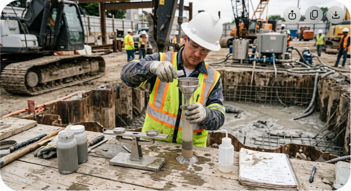
Formulating an effective bentonite slurry is a careful balancing act. If the slurry is too thin, filter cake formation fails and slurry loss spikes. If it is too thick, soil cuttings remain trapped in the mix, pumping resistance skyrockets, and tremie concrete cannot properly displace the fluid during the final pour.
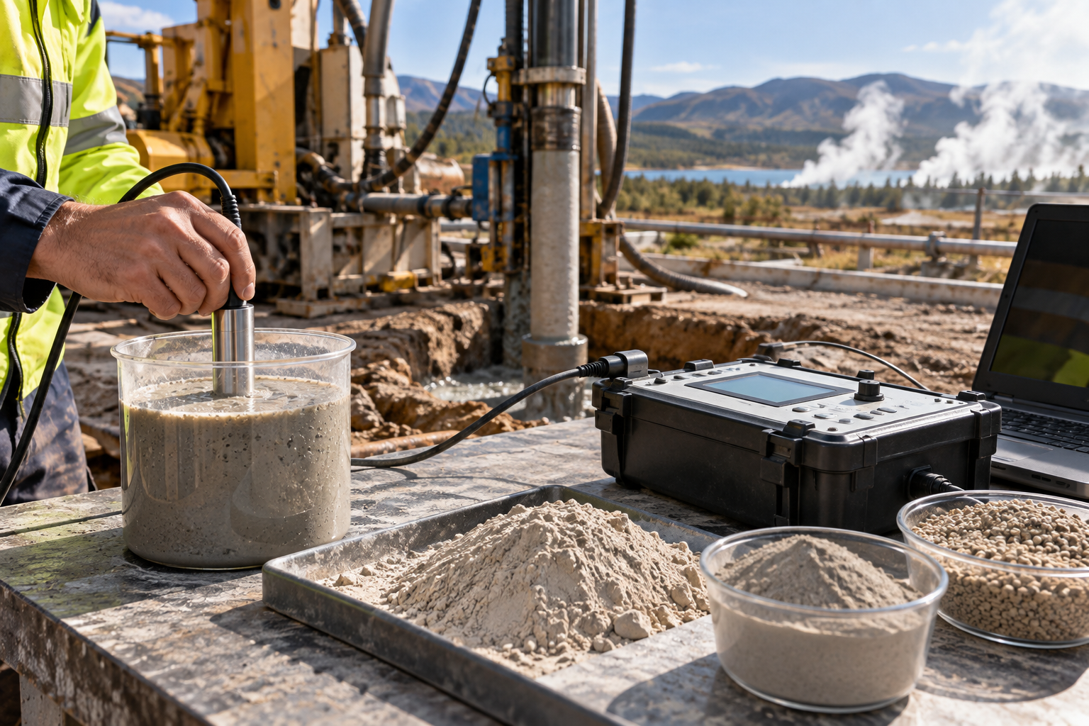
Field engineers must test slurry properties regularly using standard American Petroleum Institute (API) or European (EN) testing procedures. The primary benchmark parameters for high-performance sodium bentonite slurries include:
Measured using a standard Mud Balance. Density provides the necessary hydrostatic head to support trench walls. However, excess density usually indicates an unhealthy buildup of recirculated sand and soil fines.
Measured as the time in seconds required for 1 quart (946 mL) or 1 liter of slurry to flow through a standardized Marsh Funnel cone orifice.
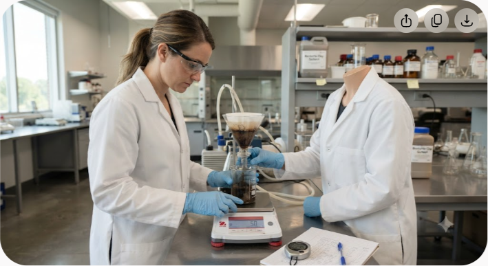
Tested using an API Filter Press under 100 psi (690 kPa) of differential pressure for 30 minutes.
Measured using digital meters or test strips. Sodium bentonite swelling depends heavily on alkaline water chemistry.
Determined using a standard 200-mesh (75 micron) sieve sand content set.
| Property | Fresh Slurry Target Range | Recycling Target Range | Pre-Pour (Tremie) Target Range | Primary Test Equipment |
|---|
| Density | 1.03?1.06 g/cm 3 | 1.05?1.12 g/cm 3 | ?1.15 g/cm 3
| API Mud Balance |
| Viscosity | 35?50 s | 35?55 s | 32?45 s | Marsh Funnel |
| pH Level | 8.5?10.5 | 8.0?11.0 | 8.5?11.0 | pH Meter / Strips |
| Fluid Loss | <15 mL | <20 mL | <15 mL | API Filter Press | | Sand Content | 0 | <4.0 | <1.0
To see bentonite slurry in action, let's walk through the full lifecycle of a concrete diaphragm wall panel excavation on a modern construction site.
Before digging begins, contractors construct two parallel, temporary reinforced concrete guide beams along the alignment of the future wall. Typically 1.0 to 1.5 meters deep, these guide walls serve three vital functions:
Dry sodium bentonite powder is mixed with clean batch water using high-shear venturi mixers. High-shear mixing is essential to break up clay clumps (referred to in the field as 'fish eyes') and ensure full separation of individual clay platelets.
Once mixed, the slurry is transferred into hydration tanks for aging. High-quality bentonite requires a minimum hydration period of 6 to 12 hours to swell fully and reach its maximum viscosity and gel strength before being pumped into active trenches.
As mechanical grabs or hydraulic desanders bite into the earth, bentonite slurry is continuously pumped into the slot directly from the storage plant. The slurry level inside the guide wall reservoir must be kept within 30 cm (12 inches) of the top of the guide wall at all times. Leaving the fluid level low reduces the critical differential hydrostatic head, drastically increasing the risk of immediate trench wall collapse.
As excavation progresses, suspended soil cuttings and fine sand mix into the slurry. The contaminated fluid is continuously pulled from the bottom of the trench using submerged pumps and routed to a specialized desanding plant on the surface.
Here, the slurry passes through vibrating scalping screens, hydrocyclones, and fine-mesh desanding screens to strip out sand particles down to 75 microns. Cleaned, desanded slurry is then returned directly to the active excavation panel.
When the panel reaches its design depth, excavation halts. The bottom of the trench is thoroughly cleaned with a de-mucking bucket or airlift pump to remove heavy debris. The slurry properties are then tested near the trench floor. If sand content or mud density is too high, fresh conditioned slurry is circulated through the panel until density drops below 1.15 g/cm 3 and sand content drops below 1 .
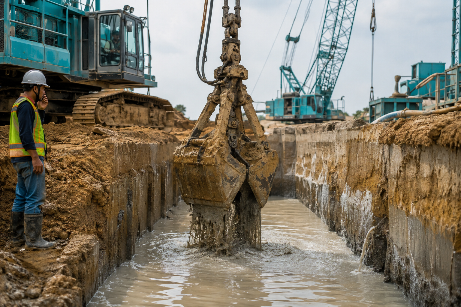
Heavy steel rebar cages are hoisted and lowered through the fluid slurry. Because clean bentonite slurry exhibits controlled viscosity, it coats the rebar without building an overly sticky, thick build-up that would compromise rebar-to-concrete bond strength.
Finally, a continuous tremie pipe is lowered to the bottom of the excavation. Self-consolidating, high-slump concrete (200 to 240 mm flow) is poured through the pipe. Because concrete is significantly denser (?2.4 g/cm 3 ) than bentonite slurry (?1.1 g/cm 3 ), the rising column of concrete forces the lighter slurry upward, displacing it entirely out of the panel.
The displaced slurry is collected at the surface guide walls, pumped back to the recycling unit, adjusted with chemical additives if necessary, and stored for the next excavation panel.
Even with precise engineering calculations, underground site conditions present unexpected surprises. Field engineering teams must know how to spot and fix slurry degradation instantly.
When the excavator hits open gravel beds, cavernous limestone, or uncontrolled urban fill, slurry can leak rapidly into the surrounding ground. If the fluid level drops below the water table, trench failure is imminent.
Concrete is rich in free calcium hydroxide (Ca(OH) 2 ?
). When fresh bentonite slurry comes into direct contact with uncured concrete, calcium ions (Ca 2+ ) replace sodium ions (Na + ) on the clay surface via ion exchange.
Calcium bentonite swells far less than sodium bentonite. This ion exchange causes clay platelets to clump together rapidly (flocculation), leading to a sudden spike in fluid loss, a drop in gel stability, and severe thinning of the mix.
2 ?
CO 3 ?
). Soda ash precipitates harmful calcium ions out of solution as insoluble calcium carbonate (CaCO 3 ?
), restoring the sodium concentration on the montmorillonite platelets.
$$ Ca^{2+} + Na_2CO_3 longrightarrow CaCO_3downarrow + 2Na^+ $$
In coastal applications or marine excavations, salty groundwater containing high concentrations of sodium chloride (NaCl) flows into the trench. The high ionic strength of salt water compresses the electrical double layer surrounding individual bentonite platelets, causing the clay structure to break down.
Over the past few decades, synthetic polymer slurries have gained market share as alternatives to traditional mineral clays. Both systems offer distinct performance advantages depending on geology, logistics, and site footprint.
| Feature / Attribute | Premium Sodium Bentonite Slurry | Synthetic Polymer Slurry |
|---|---|---|
| Primary Mechanism | Forms an impermeable surface filter cake | Penetrates soil pores to create chemical cohesion |
| Site Footprint | Large (requires hydration tanks, desanders) | Small (compact mixing, direct hydration) |
| Performance in Coarse Gravel | Exceptional (bridges wide pore gaps) | Poor (leaks easily into loose, open formations) |
| Recyclability | High durability; easily desanded mechanically | Degrades under high shear or soil contamination |
| Concrete Bond Strength | Good (if filter cake thickness remains <2 mm) | Excellent (leaves virtually no film on rebar/concrete) |
| Environmental Disposal | Inert mineral clay; simple soil neutralization | Biodegradable, but sensitive to disposal pH limits |
| Sensitivity to Salt Water | Requires specialized grade / additives | Highly sensitive; breaks down rapidly in saline water |
While polymers excel in tight urban sites with clean, cohesive soils due to their small footprint, high-yield sodium bentonite remains the gold standard for heavy civil engineering. Its ability to form a robust, physical filter cake in mixed, unstable, or highly permeable ground provides an unmatched safety margin against catastrophic structural failure.
Not all bentonite powders behave identically in deep foundation trenches. The operational reliability of your slurry relies directly on the mineral purity of the raw clay source.
Natural sodium bentonites with high montmorillonite content (>85 ) deliver inherently superior swelling capacity, rapid thixotropy, and resilient thermal stability compared to calcium bentonites that have been artificially modified with soda ash.
When sourcing bentonite for critical infrastructure projects like diaphragm walls, deep cut-off barriers, or metro station box excavations, structural engineers and piling contractors must prioritize material consistency:
Working with an established global mineral producer like Axewelledge guarantees that your project receives ultra-consistent, high-yield sodium bentonite mined directly from high-purity reserves. With strict quality control standards, integrated R&D, and massive strategic reserves, Axewelledge delivers specialized drilling and civil engineering bentonite grades formulated to meet demanding international standards (including API Spec 13A and localized civil specifications).
Whether you are excavating a 40-meter deep basement panel through difficult coastal soils or constructing heavy bridge pier foundations, securing high-purity sodium bentonite ensures your slurry holds up reliably under extreme soil and water pressures.
Bentonite slurry acts as a liquid shore during excavation. It exerts continuous outward hydrostatic pressure against trench walls while forming a thin, impermeable filter cake on the soil face. This membrane seals soil pores, stops groundwater seepage, and prevents lateral earth collapse without mechanical bracing.
Under hydrostatic pressure, bentonite slurry flows toward the exposed soil face. As water enters soil pores, micro-sized sodium bentonite clay platelets become trapped against the formation openings. They overlap rapidly to construct a tough, micro-thin barrier that halts liquid loss and transfers fluid pressure directly onto the soil frame.
Sodium bentonite features naturally high swelling capabilities, expanding up to 15 to 20 times its dry volume in fresh water. It yields superior viscosity, high thixotropic gel strength, and excellent fluid-loss control. Calcium bentonite swells significantly less and lacks the structural gelling performance required for deep foundation stability.
Contaminated slurry containing suspended sand and soil cuttings is pumped from the trench floor into a mechanical desanding plant. The fluid passes over vibrating scalping screens, hydrocyclones, and fine mesh screens to remove solids down to 75 microns before returning clean slurry to the active excavation.
Concrete is placed from the bottom of the trench upward using a submerged tremie pipe. Because concrete is substantially heavier and denser than bentonite slurry, it displaces the lighter fluid upward. The slurry is collected at the surface guide walls, desanded, chemically conditioned, and reused in subsequent panels.
To ensure total stability during your next deep excavation panel, keep these core operational rules top of mind:
prior to tremie concrete placement to guarantee clean concrete displacement and strong rebar bond integrity.

Have questions about our products? We're here to help!