Axewelledge, a leading exporter from India, specializes in high-quality Bentonite. With a commitment to excellence, we supply premium Bentonite to the Middle East and Southeast Asia markets.


North Angle Complex, 304,
150 Feet Ring Rd, Opposite Ambedkar Nagar BRTS Stop,
Madhav Park, Punit Nagar,
Mavdi, Rajkot, Gujarat 360004
© Axewelledge 2026, All Rights Reserved.
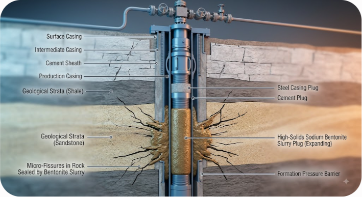
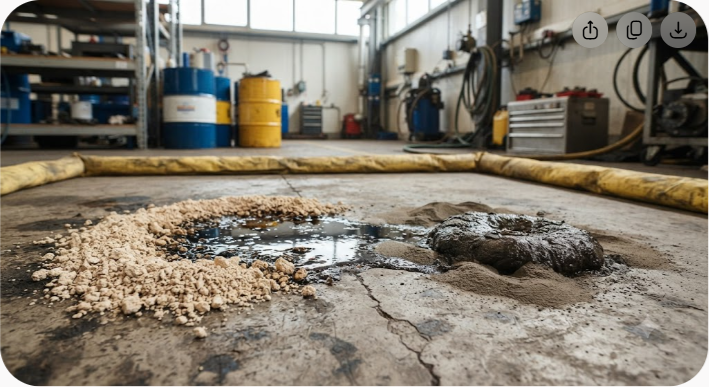
Over 3 million inactive oil, gas, and water wells dot North America alone, with hundreds of thousands more located across Europe, Asia, and the Middle East. When a well reaches the end of its operational lifespan, proper sealing serves as the final barrier against environmental contamination. If plugged incorrectly, these abandoned bores transform into active conduits for methane venting, subsurface hydrocarbon migration, and cross-contamination between drinking water aquifers and saline formations.
For decades, Portland cement remained the industry standard for Plug and Abandonment (P&A) operations. Yet long-term field data reveals a major flaw: rigid cement plugs frequently degrade over decadal timescales. Cement naturally shrinks during hydration, fractures under micro-seismic stresses, and breaks down when exposed to corrosive formation fluids such as hydrogen sulfide ($H_2S$), carbon dioxide ($CO_2$), or high-salinity brines.
High-yield sodium bentonite slurry offers a permanent solution to these structural limitations. As an expanding, self-healing clay mineral, sodium bentonite creates a flexible hydraulic seal that rigid systems cannot match. Properly hydrated sodium bentonite forms an ultra-low permeability gel matrix that expands against wellbore walls, continuously sealing micro-annuli and adapting to downhole geological movement.
This guide breaks down the engineering mechanics, hydration dynamics, field mixing ratios, and regulatory compliance rules for applying sodium bentonite slurry in P&A projects. Whether you manage offshore production rigs, onshore oil assets, or regional groundwater wells, mastering sodium bentonite slurry formulation ensures reliable zonal isolation.
Sodium bentonite is an smectite-rich clay composed primarily of sodium montmorillonite, formed by the natural weathering of volcanic ash over millions of years. Its unique molecular structure gives it extraordinary water-absorption and swelling properties that make it an ideal sealant for sub-surface isolation.
At the microscopic level, montmorillonite consists of three-layer sheets: an octahedral sheet of aluminum or magnesium sandwiched between two tetrahedral sheets of silica (a 2:1 layer clay structure). Isomorphous substitution within these crystalline layers—such as aluminum replacing silica, or magnesium replacing aluminum—creates a net negative charge across the surface of the clay platelets.
In naturally occurring sodium bentonite, exchangeable sodium cations ($Na^+$) balance this negative charge. Because the hydration energy of sodium ions is high and their ionic charge is relatively weak, water molecules readily penetrate the interlayer spaces between the clay sheets.
Montmorillonite consists of an octahedral alumina sheet sandwiched between two tetrahedral silica sheets. Exchangeable sodium cations and hydration layers rest between these three-layer sheet stacks. As fresh water enters the lattice, the sodium cations hydrate, driving the layers apart and creating a continuous crystalline lattice expansion.
When un-hydrated sodium bentonite comes into contact with fresh water, it undergoes a two-phase expansion process:
This rapid physical expansion forces the clay gel into every micro-fissure, vug, and void within the surrounding rock matrix or casing micro-annuli. Once fully hydrated under confinement within a wellbore, high-purity sodium bentonite achieves an extraordinarily low hydraulic conductivity, often ranging from $1 \times 10^{-8}$ cm/sec down to $1 \times 10^{-10}$ cm/sec.
When dry clay granules meet fresh water, they experience crystalline swelling up to 400% expansion. Further water uptake drives osmotic swelling up to 1,800% total volume increase, culminating in a dense cohesive gel with hydraulic conductivity between $10^{-8}$ and $10^{-10}$ cm/sec.
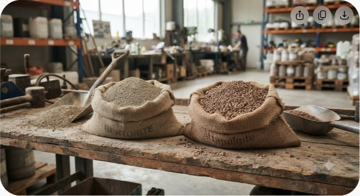
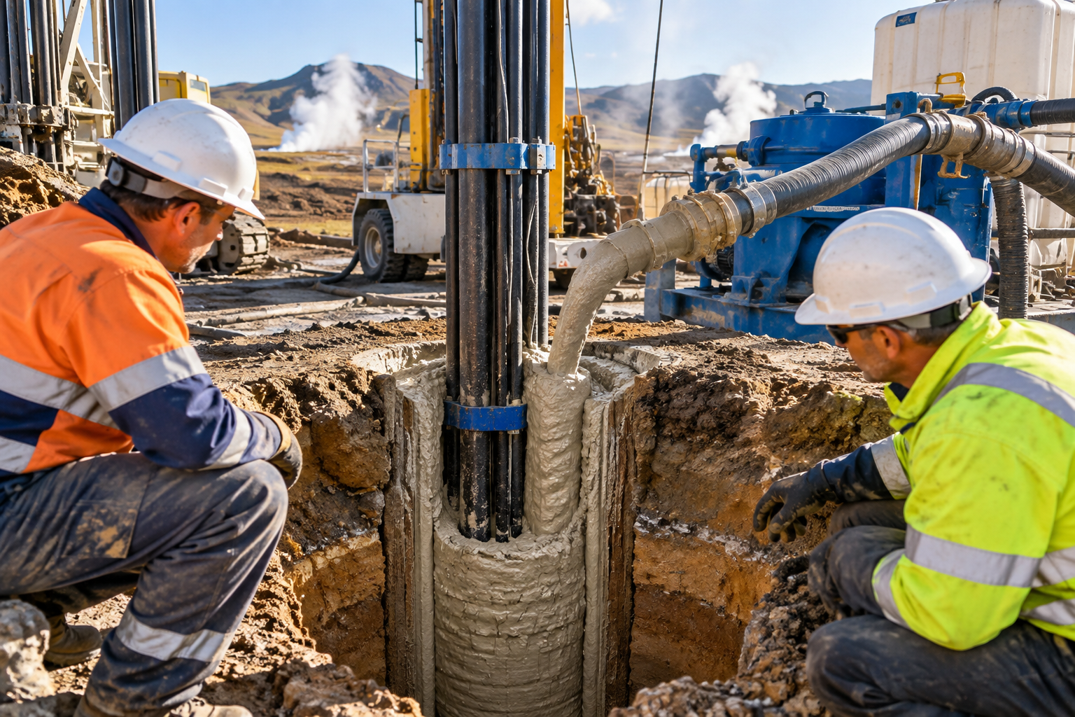
In modern P&A engineering, sodium bentonite is deployed in two primary ways: as a heavy high-solids slurry pumped through drill pipe or tubing, or as compressed pellets/granules dropped directly into shallow wellbores. In deep oil and gas P&A applications, high-solids sodium bentonite slurries are preferred because they can be precisely mixed, metered, and placed via displacement pumping.
To evaluate where sodium bentonite fits into a P&A campaign, consider how it compares to traditional Class A/G/H cements and modern thermosetting resins across critical engineering metrics:
| Engineering Property | High-Solids Sodium Bentonite Slurry | Standard Portland Cement (Class G/H) | Thermosetting Resin / Polymer |
|---|---|---|---|
| Drying/Setting Shrinkage | Zero shrinkage (Expands up to 18x dry volume) | 1% to 3% volumetric shrinkage | Minimal to zero shrinkage |
| Flexibility & Ductility | High (Self-healing plastic gel/sol) | Low (Brittle, susceptible to micro-cracking) | High (Elastomeric / Rigid matrix) |
| Long-Term Permeability | $10^{-8}$ to $10^{-10}$ cm/sec | $10^{-5}$ to $10^{-7}$ cm/sec | $< 10^{-10}$ cm/sec |
| Chemical Resistance ($H_2S$ / $CO_2$) | Exceptional (Inorganic, chemically inert) | Poor (Subject to carbonation and acid wash) | High |
| Placement Flexibility | High (Pumpable pump-and-place slurry) | High (Standard cementing equipment) | Moderate (Requires precise thermal window) |
| Material Cost | Economical | Economical to Moderate | Very High (5x - 10x cement cost) |
| Temperature Limit | Stable up to 200°C (392°F) | Stable up to high temps with retarders | Varies by resin chemistry |
While cement remains structural for supporting mechanical retainers, sodium bentonite slurry offers superior fluid isolation, long-term stability, and flexibility in non-structural zonal barriers.
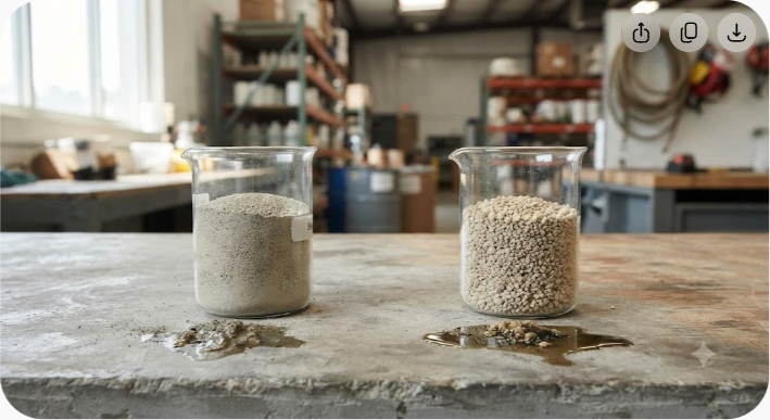
Not all bentonite is created equal. Using low-grade civil engineering bentonite or untreated calcium bentonite in a P&A well will lead to rapid flocculation, insufficient yield, and failure to seal.
Naturally occurring sodium bentonite (typically mined from high-grade deposits in North America or India) features sodium as the primary exchangeable ion in the crystal lattice. Sodium-activated calcium bentonite, on the other hand, is produced by adding soda ash (sodium carbonate) to calcium bentonite.
While soda-ash activation temporarily improves initial swelling, activated clays tend to lose their swelling capacity over long periods when exposed to high ionic strength formation waters or thermal cycling downhole. For permanent P&A operations, high-purity natural sodium bentonite with a minimum montmorillonite content of 85% is recommended.
When procuring raw bentonite for well plugging, specify compliance with API Specification 13A (Section 4 or 5) or equivalent regional standards:
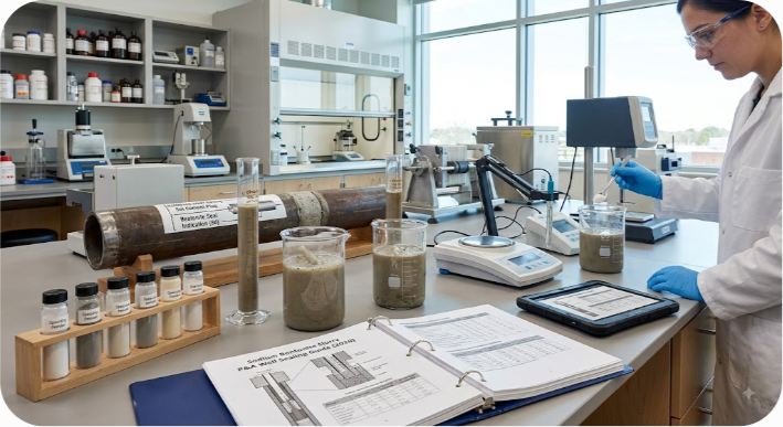
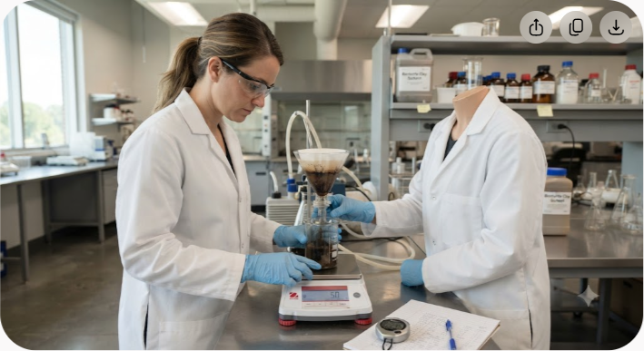
A complete P&A quality check mandates API Spec 13A compliance, greater than 85% montmorillonite content, a Free Swell Index of at least 24 mL per 2 grams, and a Liquid Limit exceeding 500%.
Designing a sodium bentonite slurry for well plugging requires balancing two competing demands: pumpability during placement and high solids content after placement.
If the slurry is too thin (low solids), the settled gel will lack the shear strength necessary to withstand differential pressures from gas or fluid zones. If the slurry is too thick (over-concentrated), dynamic viscosity will spike, causing high friction pressure in the work string and incomplete displacement of drilling fluid.
A standard P&A sodium bentonite slurry targets a solids loading between 20% and 30% by weight, producing a final slurry density of 9.5 to 11.0 lbs/gallon (1.14 to 1.32 g/cm³).
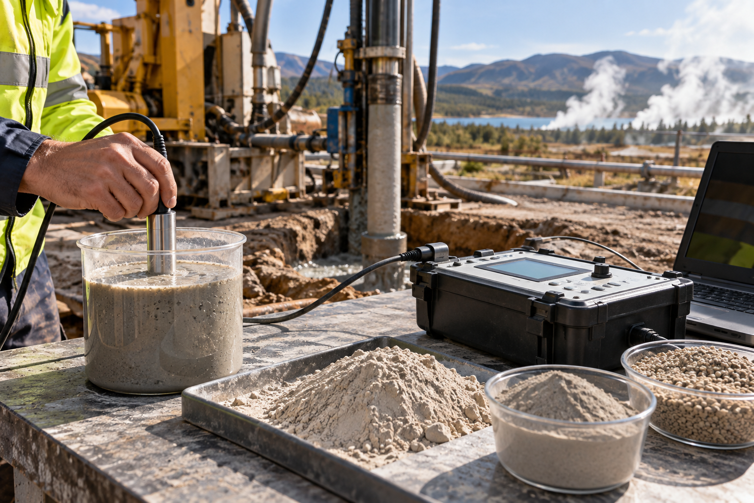
The quality of the mix water controls the hydration performance of sodium bentonite. Pre-testing makeup water on-site is essential before batch mixing:
| Water Parameter | Acceptable Range | Treatment if Off-Target |
|---|---|---|
| pH | 8.5 – 9.5 | Add Soda Ash ($Na_2CO_3$) |
| Hardness ($Ca^{2+}$ / $Mg^{2+}$) | $< 100$ ppm | Pre-treat water with Soda Ash |
| Chlorides | $< 500$ ppm | Source fresh makeup water |
Depending on wellbore geometry, depth, and formation chemistry, specialized chemical additives can optimize slurry performance:
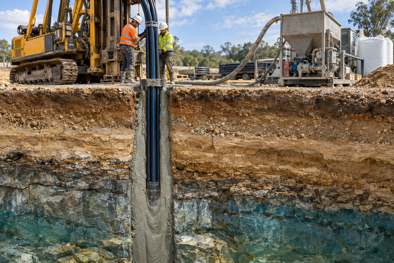
Executing a successful sodium bentonite slurry plug requires rigorous surface preparation, accurate volumetric calculations, and controlled displacement pumping downhole. Below is a detailed field procedure for an onshore P&A operation.
Before pumping bentonite slurry, the wellbore must be clean and free of mobile hydrocarbons, scale, and heavy mud solids.
Using high-shear mixing equipment is non-negotiable when preparing high-solids bentonite slurries. Low-shear paddle mixers will create unhydrated "fish eyes" (dry lumps wrapped in a hydrated gel skin), resulting in weak spots in the final plug.
The most reliable technique for placing a slurry plug is the Balanced Plug Method, utilizing work string tubing or drill pipe run to the base of the target interval.
The placement sequence progresses through four operational stages:
Accurate calculations are vital to ensure the plug covers the required vertical height and maintains sufficient hydrostatic head without fracturing surrounding formation layers.
To calculate the required volume of sodium bentonite slurry ($V_{slurry}$):
Where:
For a standard 7-inch casing ($26$ lbs/ft, internal diameter = $6.276$ inches):
If the regulatory authority requires a 200-foot continuous P&A seal interval with a 10% safety margin:
$$V_{slurry} = 0.03825 \text{ bbl/ft} \times 200 \text{ ft} \times 1.10 = 8.415 \text{ barrels (353.4 gallons)}$$
Ensure that the hydrostatic pressure exerted by the slurry column ($P_{hydro}$) exceeds formation pore pressure ($P_{formation}$) to avoid gas influx, but stays well below formation fracture pressure ($P_{fracture}$):
Where:
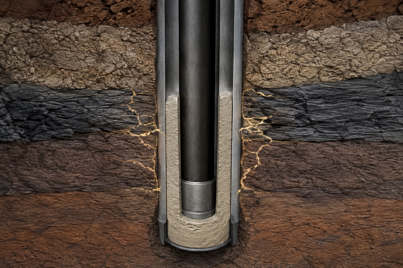
A 10.0 ppg sodium bentonite slurry plug placed at a TVD of 3,500 feet:
This hydrostatic pressure provides a stable safety margin against typical sub-surface formation fluid kick dynamics during the hydration and setting phase.
While sodium bentonite slurry offers exceptional sealing performance, complex downhole environments present challenges that must be anticipated during fluid design.
When a bentonite slurry plug contacts formation water containing high concentrations of sodium chloride ($NaCl$), calcium chloride ($CaCl_2$), or magnesium ions ($Mg^{2+}$), the osmotic swelling pressure drops rapidly. High ionic strength suppresses the electrical double layer around the clay platelets, leading to premature gel collapse or syneresis (water bleeding).
At elevated bottom-hole static temperatures (BHST), montmorillonite can undergo a slow chemical transformation into non-swelling illite clay (illitisation) in the presence of potassium ions ($K^+$).
In wells penetrating shallow gas zones, gas bubbles can migrate up through a liquid slurry before the clay matrix develops sufficient static gel strength.
| Downhole Challenge | Primary Driver | Mitigation Strategy |
|---|---|---|
| High Salinity Brine | Cationic Charge Suppression | Pre-hydrate in fresh water + CMC polymers |
| High Temperature ($>150^\circ\text{C}$) | Illitisation Transformation | Use natural high-purity Na-bentonite; avoid $K^+$ |
| Gas Channeling | Slow Static Gel Strength Build | Add thixotropic polymers for rapid gelation |
Plugging regulations vary by jurisdiction, but regulatory bodies worldwide are increasingly accepting high-solids sodium bentonite slurries alongside or in combination with traditional cement plugs.
Examining real-world P&A operations demonstrates how sodium bentonite slurry solves complex well sealing challenges in the field.
The project moved from initial failure to complete isolation through three distinct phases:
To ensure consistent performance on your next well plugging campaign, use this field readiness checklist:
Achieving long-term zonal isolation requires uncompromised raw material quality. At Axewelledge, we leverage over 60 million tons of natural sodium bentonite reserves from our high-grade mining operations in India to supply the oilfield, construction, and environmental sectors worldwide.
Our P&A-grade sodium bentonite is processed with state-of-the-art refinement technology to deliver high Montmorillonite content, rapid hydration capacity, and stable high-yield rheology under downhole conditions. With strategic processing facilities, strict API quality compliance, and robust export logistics supporting clients across the Middle East, Southeast Asia, North America, and beyond, Axewelledge delivers the raw material performance your engineering team needs for critical decommissioning projects.
If you are planning an upcoming plug and abandonment campaign, reach out to our technical mineral specialists to discuss custom powder specifications, bulk export logistics, and technical laboratory testing reports.
Plug and abandonment is no longer just about filling a hole with cement and moving on. It is about establishing continuous geological integrity that outlasts human engineering timescales. Sodium bentonite slurry provides a resilient, expanding, self-healing hydraulic seal that addresses the fundamental vulnerabilities of rigid setting materials.
By selecting high-purity natural sodium bentonite, controlling makeup water quality, designing high-solids mix ratios, and executing precise balanced-plug placement techniques, operator teams can eliminate orphan well emissions, safeguard groundwater reserves, and fulfill environmental compliance commitments with complete confidence.

Have questions about our products? We're here to help!