Axewelledge, a leading exporter from India, specializes in high-quality Bentonite. With a commitment to excellence, we supply premium Bentonite to the Middle East and Southeast Asia markets.


North Angle Complex, 304,
150 Feet Ring Rd, Opposite Ambedkar Nagar BRTS Stop,
Madhav Park, Punit Nagar,
Mavdi, Rajkot, Gujarat 360004
© Axewelledge 2026, All Rights Reserved.
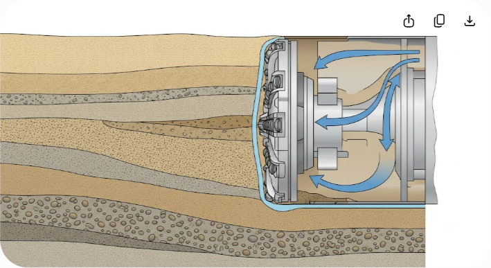
A slurry shield Tunnel Boring Machine (TBM) fails at the cutterhead long before mechanical breakdown occurs. When face support pressure drops by just 0.2 bar in soft, water-bearing ground, the risk of surface settlement or face collapse spikes dramatically. Soil conditioning using bentonite slurry serves as the primary defense against catastrophic ground loss, uncontrolled water ingress, and excessive cutterhead wear.
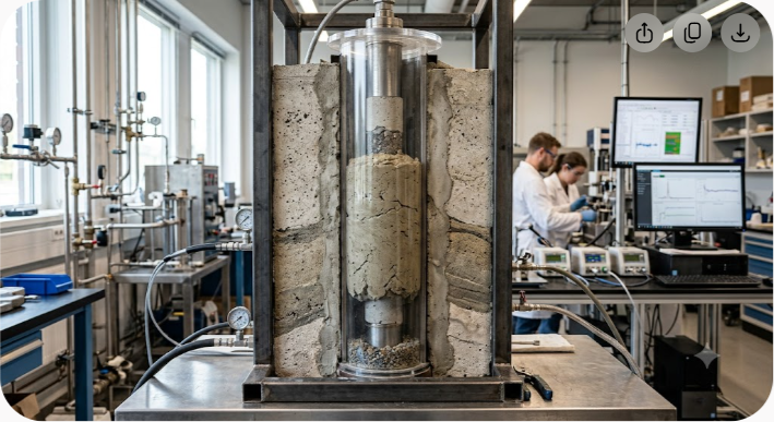
Bentonite slurry performs two roles simultaneously: it acts as a hydraulic support medium and a transport fluid. By forming a low-permeability membrane—known as a filter cake—on the excavation face, high-yield sodium bentonite transfers hydraulic pressure directly to the soil skeleton. This pressure balances external pore water and earth pressures, allowing the cutterhead to rotate smoothly without over-excavating or blinding the cutting tools.
Achieving optimal TBM soil conditioning requires balancing slurry density, plastic viscosity, yield point, and fluid loss. Under-conditioned ground leads to rapid tool wear, torque spikes, cutterhead clogging, and surface settlement. Over-conditioned or poorly formulated slurry leads to separation failures in the treatment plant, higher environmental disposal costs, and unnecessary chemical expenses. Controlling bentonite slurry performance remains the single most impactful operational lever for maintaining daily tunneling advance rates.
Understanding how bentonite conditions soil during a TBM drive requires examining its mineral structure. High-grade commercial bentonite consists primarily of montmorillonite, a 2:1 expandable smectite clay mineral. Each microscopic sheet comprises an aluminum octahedral layer sandwiched between two silicon tetrahedral layers.
When sodium bentonite comes into contact with water, water molecules hydrate the exchangeable sodium ions between these layers. This reaction triggers expansion, causing the clay particles to delaminate into microscopic platelets. The negatively charged surfaces repel one another while interacting with positively charged edges, creating a three-dimensional lattice structure in suspension.
This microscopic matrix gives hydrated bentonite slurry its distinct rheological characteristics: thixotropy, high swelling capacity, and dynamic yield stress. Under static conditions—such as when the TBM stops during segment ring installation—the slurry gels to keep heavy soil cuttings in suspension. Under dynamic shear conditions—when the cutterhead rotates or pumps run—the gel thins out, lowering viscosity to ensure efficient fluid circulation.
Soil conditioning strategies differ fundamentally based on whether the drive uses an Earth Pressure Balance (EPB) TBM or a Slurry Shield TBM:
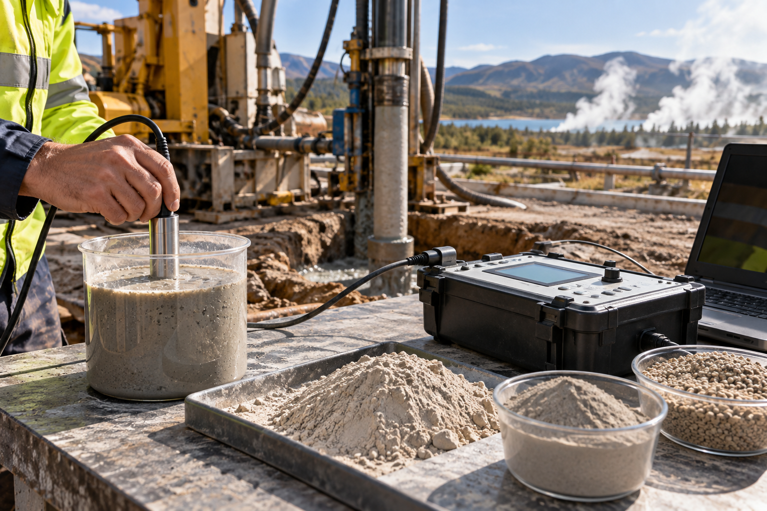
Managing bentonite slurry performance requires systematic field testing both before injection and during return flow from the excavation chamber. Deviating from established control bands compromises face stability and overburdens the surface treatment facility.
Measured using a mud balance, fresh sodium bentonite slurry enters the tunnel at densities between 1.03 and 1.08 g/cm³. As fluid mixes with excavated solids in the working chamber, return slurry density rises to 1.15–1.30 g/cm³. While higher density increases support pressure, an excessively dense slurry indicates silt saturation, which escalates pump wear and line friction.
Field technicians measure Marsh funnel viscosity by recording the seconds required for 946 mL (1 quart) of slurry to flow through a standard orifice. Fresh slurry targets 35 to 50 seconds. Return slurry exceeding 65 seconds signals fine-particle contamination, requiring immediate desanding or hydrocyclone processing at the surface plant.
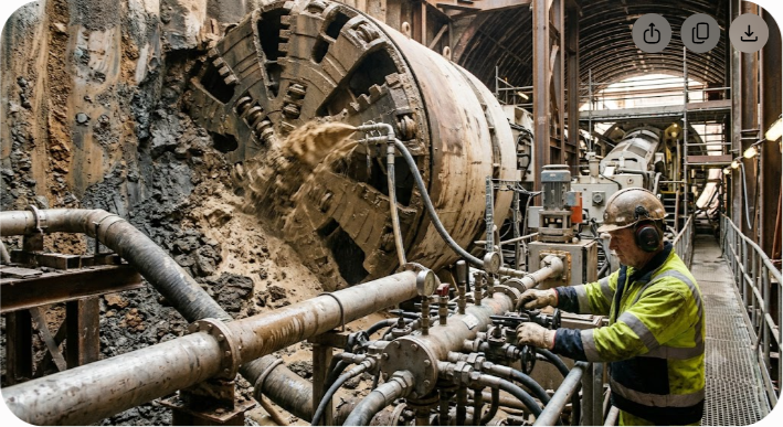
Using a rotational viscometer, engineers measure Yield Point (YP)—the stress required to initiate fluid movement—and Plastic Viscosity (PV), which reflects internal friction. A balanced YP/PV ratio maintains cuttings transport without causing pressure spikes:
$$\text{YP/PV Ratio} = \frac{\text{Yield Point (lb/100 ft}^2\text{)}}{\text{Plastic Viscosity (cP)}}$$
Targeting a ratio between 0.7 and 1.2 ensures strong suspension characteristics without generating turbulent flow spikes inside the working chamber.
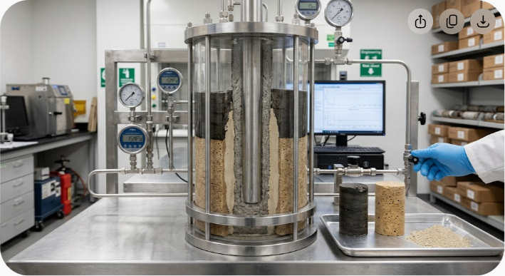
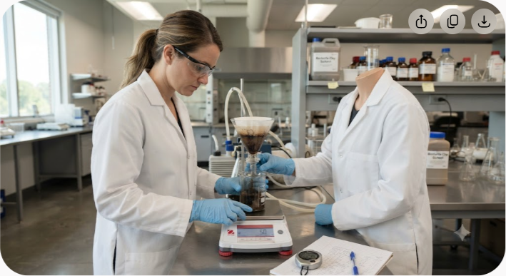
An API filter press operating at 100 psi (6.9 bar) for 30 minutes measures filtrate volume loss and cake thickness. High-grade sodium bentonite maintains fluid loss below 15 mL while forming a tough filter cake under 2.0 mm thick. A thick, spongy cake (>4.0 mm) increases cutterhead drag, spikes drive torque, and risks blinding suction ports.
Gel strength measures the internal structural strength that develops under static conditions. A low 10-second gel strength ensures smooth pump restarts after ring building, while a stable 10-minute gel strength prevents cobbles and gravel from settling to the bottom of the excavation chamber during maintenance halts.
| Parameter | Test Method | Fresh Slurry Target | Return Slurry Limit | Operational Impact |
|---|---|---|---|---|
| Density | Mud Balance | 1.03–1.08 g/cm³ | < 1.30 g/cm³ | Balances face pressure against over-pressurization |
| Marsh Viscosity | Marsh Funnel | 35–50 s | < 65 s | Dictates pumpability and dynamic head loss |
| Yield Point | Rotational Viscometer | 15–25 lb/100 ft² | < 40 lb/100 ft² | Controls cuttings suspension during stops |
| Fluid Loss | API Filter Press | < 15 mL / 30 min | < 25 mL / 30 min | Governs cake permeability and water loss |
| Filter Cake | API Filter Press | 1.0–2.0 mm | < 3.5 mm | Prevents cutterhead drag and clogging |
| pH Level | pH Meter / Strips | 8.5–10.5 | 8.0–11.0 | Maintains full montmorillonite hydration |
No single slurry formulation performs universally across varying geologies. Soil conditioning parameters must adapt dynamically to changes in grading, soil permeability, and pore water chemistry along the tunnel alignment.
| Permeability Range | Soil Classification | Primary Conditioning Mechanism | Recommended Additives |
|---|---|---|---|
| High ($> 10^{-3}\text{ m/s}$) | Coarse Gravel & Cobbles | Deep penetration control & void bridging | Bentonite + Coarse Fillers + PHPA Polymers |
| Medium ($10^{-3}\text{ to } 10^{-5}\text{ m/s}$) | Fine to Medium Sands & Silts | Impermeable filter cake membrane formation | Standard High-Yield Sodium Bentonite |
| Low ($< 10^{-6}\text{ m/s}$) | High-Plasticity Stiff Clays | Anti-adhesion & mechanical lubrication | Bentonite + Non-Ionic Surfactants / Dispersants |
In highly permeable soils, unconditioned bentonite slurry flows into large pore voids without forming an external cake, causing pressure loss. To fix this, technicians add Coarse Material Fillers (CMF) like ground calcium carbonate or cellulosic fibers alongside high-molecular-weight polymers (PHPA). These additions bridge pore voids, establishing a structural foundation for bentonite membrane deposition.
Fine sands and silts represent ideal ground for bentonite tunneling. Pore throat dimensions allow clay particles to filter out at the immediate face interface, rapidly building a thin, tough membrane. Support pressure transfers effectively into effective stress across the soil skeleton, stabilizing the excavation face.
Cohesive clay formations present a different challenge: cutterhead clogging and clay accretion. Native sticky clays adhere to metal surfaces, cutter disc assemblies, and chamber walls. Using un-modified bentonite can worsen sticky buildup. Injecting anti-adhesion polymers or liquid dispersants alters clay surface charges, preventing balling and keeping drive torque within safe operational limits.
Saline groundwater (>10,000 ppm Cl?) compresses the electrical double layer of standard clays, causing rapid flocculation and settling. Marine tunneling drives require pre-hydrated natural sodium bentonite blended with salt-tolerant polymers like Carboxymethyl Cellulose (CMC) or Polyanionic Cellulose (PAC) to protect hydration and filtrate control.
One of the most frequent errors on job sites is pumping under-hydrated bentonite. Montmorillonite requires adequate time, temperature, and shear energy to expand fully and achieve its ultimate viscosity and yield stress.
Mixing raw sodium bentonite powder with water follows three clear stages:
Pumping bentonite after only 20 minutes of mixing wastes raw material. Unswollen clay particles enter the working chamber, hydrate under cutterhead shear, and cause unpredictable viscosity spikes that disrupt pressure control systems. Batch plants should maintain a minimum maturation time of 4 to 6 hours in agitated holding tanks prior to line injection.

The water used to hydrate bentonite directly impacts raw material performance. High hardness or incorrect pH restricts swelling capacity:
Field teams must diagnose and correct slurry anomalies quickly to protect workers, maintain face stability, and keep the drive on schedule.
Modern tunneling projects enforce strict environmental rules regarding slurry recycling and final waste management.
To minimize fresh water and raw bentonite consumption, projects process return slurry through sequential treatment steps:
As slurry cycles continuously through the system, fine clay particles from the cut ground build up, raising plastic viscosity without improving gel strength. When mechanical separation cannot keep slurry density below 1.25 g/cm³, a portion of the fluid must be purged and replaced with fresh bentonite mix.
Discharging untreated liquid bentonite slurry into municipal drains or waterways is prohibited due to high turbidity and alkalinity. Waste slurry undergoes mechanical dewatering:
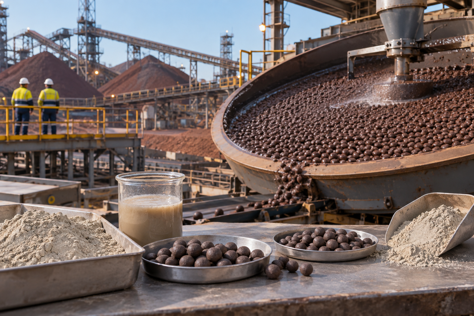
Every meter of soft ground excavated by a slurry shield or EPB TBM depends on raw bentonite quality. Subpar minerals cause fluid loss spikes, poor gel strength, higher consumption, and expensive downtime when slurry systems fail under high hydrostatic heads.
As India's largest mine owner and exporter of sodium bentonite, Axewelledge ranks among the top global producers, backed by over 60 million tons of natural high-grade reserves. With more than 15 years of geotechnical mineral experience, advanced R&D, and modern refinement facilities, Axewelledge supplies specialized sodium bentonite formulated for pressurized mechanized tunneling.
Whether driving urban metro lines beneath sensitive structures or excavating subsea utility tunnels, Axewelledge delivers bentonite featuring rapid hydration, high swelling volumes, low filtrate loss, and thermal stability. Supported by strategically located processing plants in India and regional distribution networks across the Middle East, Southeast Asia, and globally, Axewelledge provides reliable mineral solutions that keep tunneling projects moving forward.
Contact the engineering team at Axewelledge to request technical data sheets, coordinate trial testing, or formulate custom bentonite slurry solutions for your upcoming tunneling drive.

Have questions about our products? We're here to help!